
fan 220v ac speed control
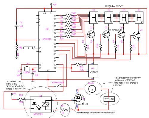
A comprehensive electronic schematic for the described AC fan speed control circuit can be developed to incorporate the functionalities outlined. The circuit will feature three fixed resistors, each connected in series with a transistor switch. The transistors will be controlled by a microcontroller or logic circuit, allowing for precise selection of the desired fan speed.
The triac will be used for controlling the AC power to the fan, with a diac providing the necessary triggering for the triac. The variable resistor can be replaced with a combination of fixed resistors, allowing for discrete control of the fan speeds. Each transistor will be connected to its respective fixed resistor, and when activated, will effectively change the resistance seen by the triac, thus adjusting the fan speed.
To ensure smooth operation, a small capacitor can be connected in parallel with the variable resistor to filter any noise and provide a stable trigger signal to the triac gate. The PWM signals can be generated by the microcontroller, where the duty cycle can be adjusted based on the selected speed setting.
Additionally, safety considerations should be taken into account by incorporating fuses or circuit breakers to protect the circuit from overcurrent situations. Proper heat dissipation measures for the triac and transistors should also be implemented to prevent overheating during prolonged operation. This design will provide a reliable and efficient means of controlling the speed of an AC fan using modern electronic components.if your AC fan have 3 button (like i have), button 1 (for low speed), button 2 (half speed), and button 3 (high speed), you can use Relay for switch the speed changing that button. But if your AC fan have 3 button (like i have), button 1 (for low speed), button 2 (half speed), and button 3 (high speed), you can use Relay for switch the speed
changing that button. I have built a circuit which works with Relays and my 2 bit instructions for 25%, 50% and 100% but it requires three relays and three AC Fan dimmers (ready made from market). I actually wanted to use Triac because relay logic is old and Relays burn easily and have a very small life as compared to Triac.
in AC, the speed is proportional to amount of energy given to fan/bulb. which is again proportional to the area under the curve of AC voltage. e. g. here i shows a figure where three AC channels are switched at different times. you can see the AC wave delivered to the device is lesser than the original AC (Yellow curve). so the area under the AC curve is different in all cases and hence your o/p voltage varies. there is no PWM remember. Ajay i have seen your Home Automation software and how you use "lwidth" for generating PWM. I want to do similar thing but i need to generate 3 PWM as mentioned in my post above. AC Fan speed is control by a triac + diac + a VARIABLE Resistor that actually (with the help oa small cap) trigger the gate of Tric at various delay (according to the vale of variable RESISTOR) due to that delay tric get ON for that much time only. U break that variable resistor into= three fix resistor and switch them in to series with the help of transistor that will be control by your logic state.
for example. if fan speed is controll fromm full to minimum by 500k resistor= use four 150k fix resistor in series = 600k and across each 150k resistor use (in parallel) a transistor or a opto when a transistor is switched on then 150k resistor is reduce to ~1k and 600k will be reduce to 450k and fan speed will increase. try and inform 🔗 External reference
Related Circuits
How can a 1950 Studebaker be enhanced? By installing an iPod Nano in the dashboard. The team at MAYA Design created a touch-controlled sound system for this project, referred to as the "Nano-Baker" or "Stude-iPod," utilizing a pair of...
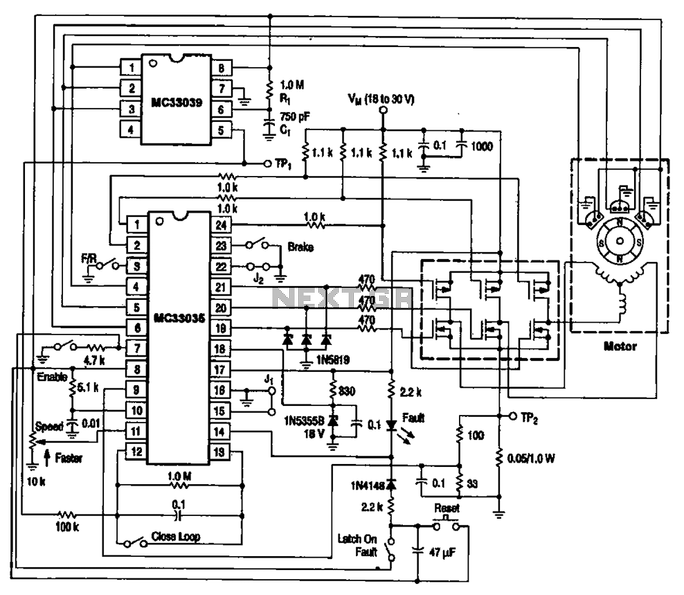
The brushless DC motor control circuit utilizing the MC33035 and MC33039 chips employs a combination of control circuits as illustrated in the figure. The primary components include the MC33035 motor control chip, the MC33039 brushless motor adapter, field effect...
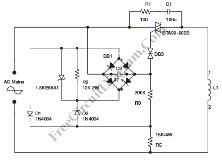
A step-down circuit is utilized to approximately halve the RMS voltage between the line input and the inductive load (L1), as illustrated in the circuit diagram below. A turn-on delay of about 7 ms is achieved through the combination...
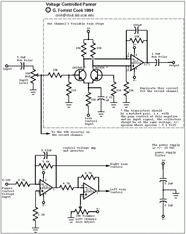
The control voltage is fed into the first half of a 1458 op-amp, this stage inverts the signal and sets the offset and gain for the right channel gain control circuit. This signal is then fed into the second...
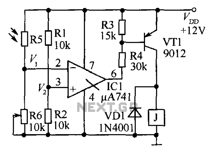
The circuit functions as a precision bright light control circuit, operating independently of power supply voltage and ambient temperature. Resistors R1, R2, R6, and the photosensitive resistor R5 form a two-arm Wheatstone bridge. The precision bright light control circuit utilizes...
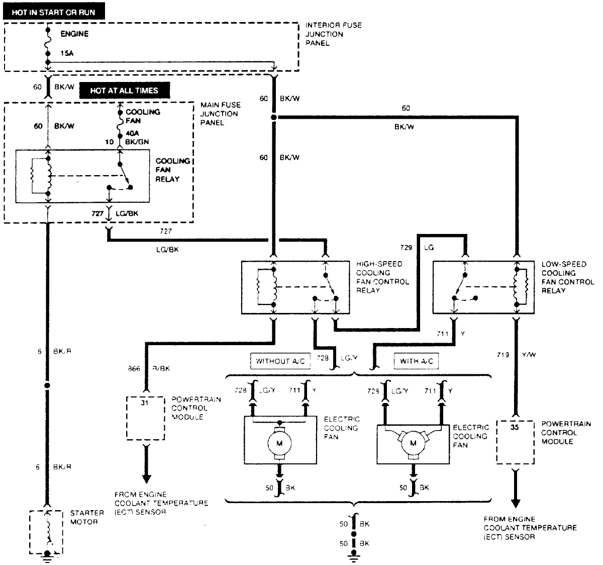
A 1995 Ford Escort wagon equipped with a 1.9-liter engine and a 5-speed manual transmission is experiencing issues with the cooling fan not activating automatically when the engine temperature rises. Testing revealed that the fan operates when directly powered....