Fantastic Simulated Laser Circuit

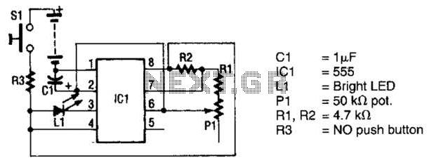
The circuit utilizes a 555 timer integrated circuit (IC) to drive an ultrabright LED. The output generated is a pulsing red light that can be focused using lenses. An ultrabright Stanley LED, which produces an output of 300 millicandela, is connected to pin 3 of the 555 timer IC. This IC is configured as an astable multivibrator, with its frequency determined by resistors R1, R2, capacitor C1, and potentiometer P1. The frequency can be adjusted by modifying the resistance of P1, allowing the output to transition from a slow blink to a rapid pulse. Additionally, resistor R3 is employed to limit the current flowing into the circuit, thereby protecting both the LED and the IC from damage due to excessive current. Switch S1 is used to apply power to the circuit when its button is pressed.
The circuit operates by utilizing the 555 timer in an astable mode, which allows it to continuously oscillate between high and low states. The frequency of oscillation is determined by the time constant created by the combination of resistors R1 and R2 in conjunction with capacitor C1. The adjustable potentiometer P1 provides flexibility in tuning the frequency, enabling users to achieve the desired rate of blinking or pulsing for the LED.
When the circuit is powered, the 555 timer generates a square wave output at pin 3, which drives the ultrabright LED. The LED's brightness and pulsing frequency can be visually adjusted, making this circuit ideal for applications requiring variable light output. Resistor R3 plays a critical role in ensuring the longevity of the components; it limits the current to a safe level, preventing potential damage to the LED and the 555 timer IC.
The inclusion of switch S1 allows for convenient control of the circuit's operation, enabling the user to turn the circuit on and off as needed. The design of this circuit is straightforward, making it accessible for hobbyists and professionals alike, while also providing a practical solution for creating variable light effects using simple electronic components. The circuit uses a 555 timer IC to power an ultrabright LED. The output is a pulsing red light that can be projected using lenses. An ultrabright Stanley LED, capable of 300-millicandle output, is tied to pin 3 of the 555 timer IC. That IC has been configured as an astable multivibrator. The frequency of this multivibrator is controlled by Rl, R2, CI, and PI. You can vary the frequency by adjusting PI, which changes the output from a slow blinking to a fast pulsating light. Resistor R3 is used to limit the current flowing into the circuit to a safe value, to prevent the LED and the IC from burning out. Switch SI applies power to the circuit when its button is pressed.


