
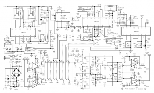
FDM stereo decoder
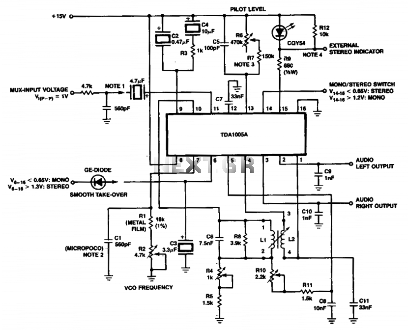
Coil data: Inductance (L) is 2.6 mH, quality factor (Qi) is -35, and minimum quality factor (Qmin) is 30. The coil has 357 turns, with dimensions E3.4 and N3 4, constructed using a wire diameter of 0.09 mm, achieving a 100% fill factor.
The circuit described incorporates various components essential for its operation. The micropoco capacitor, characterized by its temperature coefficient, plays a crucial role in stabilizing the circuit's performance across varying thermal conditions. The specified temperature coefficient indicates the capacitor's sensitivity to temperature changes, which is critical in precision applications.
The use of a fixed resistor, such as the 620kΩ resistor, ensures that the circuit maintains a consistent switching threshold, which is particularly important for digital circuits where signal integrity is paramount. The guaranteed switching level of less than 16mV allows for reliable operation in low-voltage scenarios, minimizing the risk of false triggering due to noise.
The coil data provided indicates an inductive component with specific characteristics that contribute to the overall circuit functionality. The inductance value of 2.6 mH suggests that the coil can store a significant amount of energy in its magnetic field, which is beneficial in applications such as filtering or signal conditioning. The quality factor (Qi) of -35 and minimum quality factor (Qmin) of 30 provide insight into the coil's efficiency and performance, with higher quality factors indicating better performance in resonant applications.
The construction details of the coil, including the number of turns (357) and the wire diameter (0.09 mm), suggest careful design considerations to optimize the coil's performance. The mention of a scrambled winding technique may imply that the coil is designed to reduce parasitic capacitance and improve overall efficiency, which is essential in high-frequency applications.
In conclusion, the circuit's design integrates a micropoco capacitor, a fixed resistor for switching stability, and a well-defined coil, all of which contribute to its robustness and reliability in various electronic applications. The ability to utilize either the LEO circuit or an external stereo indicator provides flexibility in implementation, catering to different user requirements or preferences. For other input structures see Figures 6 to 11; shown here with PC-filter (Figure ß). The micropoco capacitor has a temperature coefficient of 125.10"6i 60.10" k"1. In simplified circuits a fixed resistor (e.g. 620k) can be used for a guaranteed switching level Of < 16mV. Either the LEO circuit or an external stereo indicator can be used. Coil data: L, l-2.6mh qi.-35; qmin-30 - 357W turns; E3.4 N3 4 « £97 ft turns: scrambled wound with wire diameter 0.09mm, - 100% =» T2%. 🔗 External reference
Related Circuits
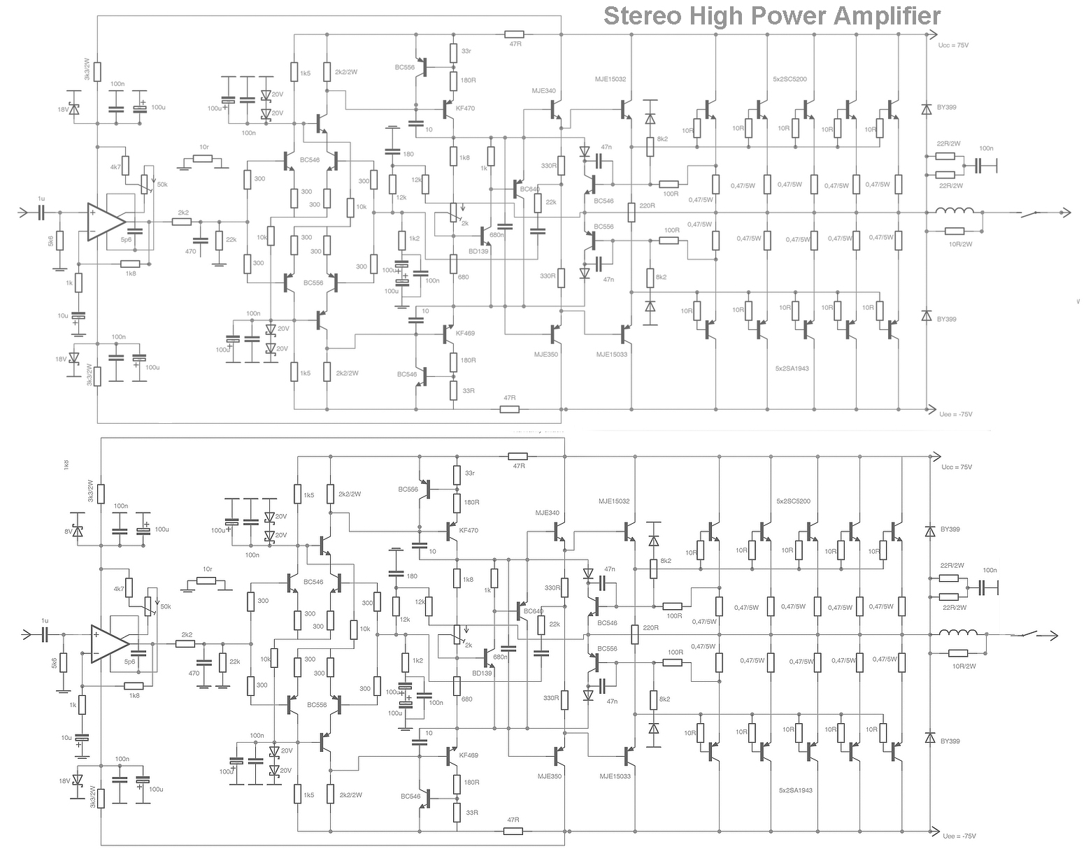
This is a stereo amplifier circuit that delivers high output power and excellent sound quality. The amplifier circuit features a very high gain output stage, which can result in signal noise deterioration. It is capable of providing an output...
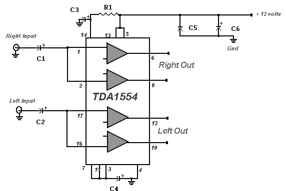
A 22 Watt stereo amplifier circuit diagram is presented. This circuit can be utilized for audio home amplifiers as well as car audio amplifiers. It features a straightforward design, is cost-effective, and is very easy to assemble, making it...
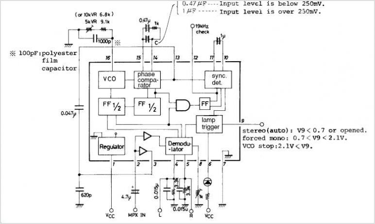
The LA3370 is a multiplex integrated circuit (IC) designed for FM car stereo applications. It performs two primary functions using the intermediate frequency (IF) meter output voltage: 1. Stereo Noise Control (SNC), which effectively reduces noise specific to FM...
The schematic diagram of the MS Decoder may appear complex, but it is relatively straightforward. Initially, both the Mid and Side signals are buffered using unity gain inverting buffers, which are constructed around IC1b and IC2b. This buffering serves...
This audio amplifier design employs two LM3886 chips per channel in a parallel configuration, based on the PA100 parallel amplifier detailed in National Semiconductor's application note AN1192. It can deliver approximately 50W into an 8-ohm speaker and 100W into...
The recent availability of a broad line of truly high-performance consumer integrated circuits makes it possible to construct a high-quality, low-noise, low-distortion electronic system. The emergence of advanced consumer integrated circuits has significantly transformed the landscape of electronic design, enabling...