
22 Watt Stereo Amplifier
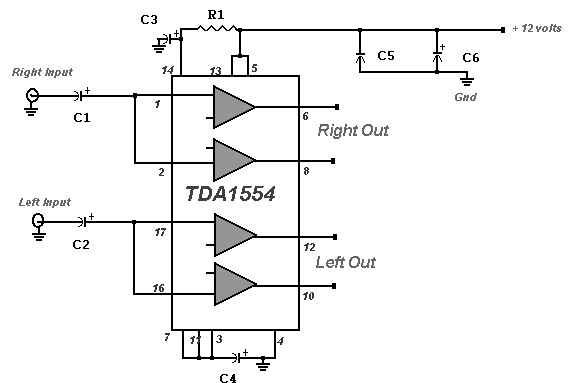
The 22 Watt stereo amplifier circuit employs the TDA1553 integrated circuit, which is designed for high-efficiency audio amplification. The TDA1553 is a Class-B amplifier, known for its ability to deliver quality sound output while minimizing distortion. The circuit typically includes a few passive components such as capacitors and resistors, which are essential for filtering and stability.
In the schematic, the input stage is connected to the audio source, such as a car stereo receiver. The amplifier's output is directly linked to the speakers, ensuring that the audio signal is amplified effectively. The circuit design should include decoupling capacitors to filter out any noise from the power supply, thereby enhancing the overall audio quality.
The use of the TDA2004 in conjunction with the TDA1553 allows for a robust amplification stage, capable of handling the demands of car audio systems. The TDA2004 serves as a secondary amplifier stage, providing additional power handling and output capabilities. It is important to incorporate proper heat dissipation methods, such as heatsinks, to prevent thermal overload during operation.
When assembling the circuit, attention must be paid to the orientation of the components and the connections to avoid short circuits. Additionally, ensuring that the speaker is isolated from the chassis ground is critical to prevent potential damage to the integrated circuits. This amplifier circuit is ideal for those seeking an affordable and efficient solution for enhancing audio performance in vehicles or home audio systems.22 Watt Stereo Amplifier circuit diagram. This circuit can be used for audio home amplifier and car audio amplifiers. It is extremely simple design, inexpensive and very easy to build. Even a newbie hobbyst will easy assemble this circuit. The scheme given here is a car stereo amplifier circuit can be used in That car or other vehicle. The circuit is basedTDA1553, which is aClass-Baudioamplifier. As you can see this circuitisverysimple, consisting onlyof theICand thecapacitor6. Here is a circuit diagram of car stereo. This 20w car audio amplifier circuit described hereoffers a20 wattboosterthatwillallow youtorealize thepower amplifierwith which one canincrease the poweroutputfromthe carstereoup to20Wattsmaximum. The inputINis connected to theoutputof thereceiver, Uoutputis connectedto the speakeras shownoncaraudioamplifierscheme.
It is veryimportanttoensurethat thespeakerhas no connection tothe chassis(ground)ifnot, the integrated circuitIC1, aTDA2004will. 🔗 External reference
Related Circuits
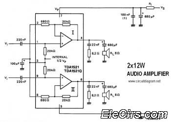
This is a stereo audio amplifier circuit that delivers 12W output power for each audio channel. The circuit is constructed using a single integrated circuit, the TDA1521 or TDA1521Q, and is supported by a minimal number of external components. The...
The RF amplifier utilizes noiseless feedback via the drain-gate capacitance, incorporating an inductor in the source lead to achieve the required 90-degree phase shift between the gate voltage and channel current. The RF amplifier is designed to enhance signal strength...
The power used for realignment is considered a loss in the context of the overall circuit. Due to the hysteresis loss in the saturable-core reactor, the power gain is relatively low. Adding a rectifier to the load circuit can...
The circuit for the power amplifier has a power output of up to 1500W RMS and is commonly utilized in outdoor sound systems. The final image displays a series of power amplifiers that utilize 10 sets of power transistors....
Nice small audio amplifier which use only few parts to give good quality sound. This amp can be used as a simple booster, the heart of a more complicated amplifier or used as a guitar amp. Although not perfect,...
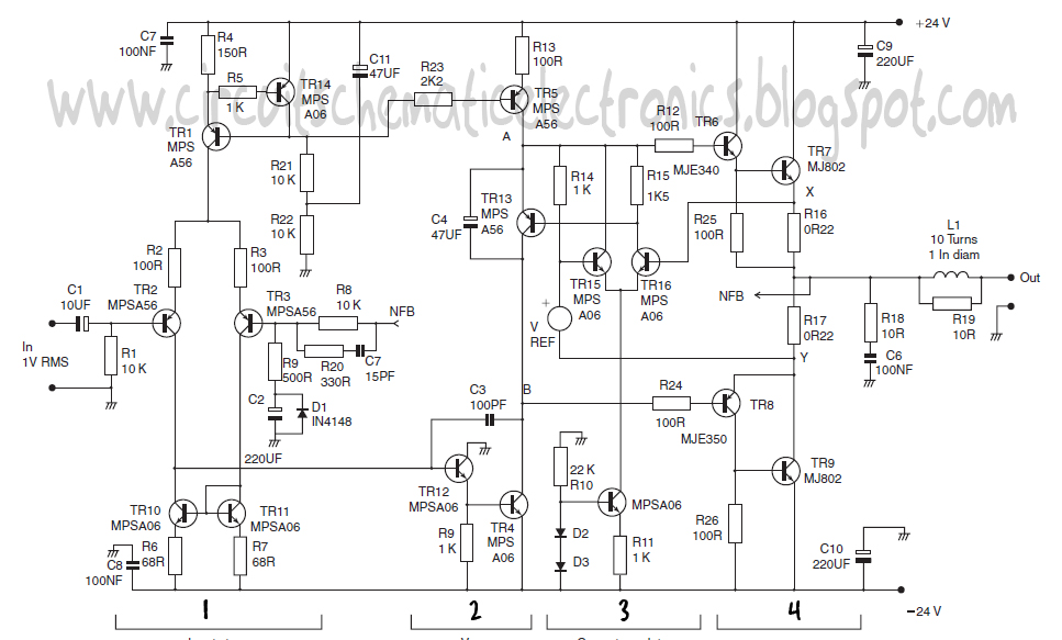
This design schematic represents a Class A power amplifier. It closely matches the operating parameters of Class B to facilitate comparison, particularly with a negative feedback (NFB) factor of 30dB at 20 kHz. The front end is similar to...