
Field strength meter 1-150Mhz
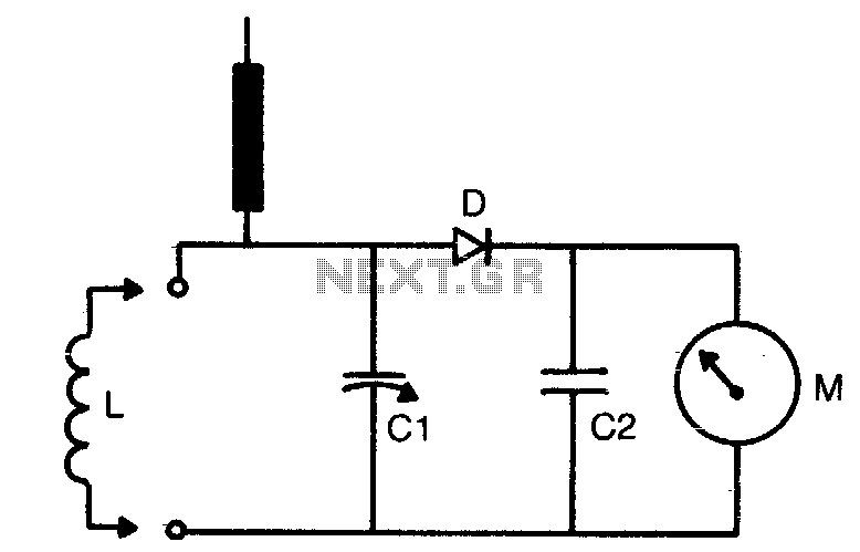
The circuit described is a tunable oscillator or a similar RF circuit where the tuning range is critical for its operation. The coil (L) serves as the inductor in the resonant circuit, and its physical dimensions, such as the number of turns, diameter, and core material, will influence both the inductance value and the frequency range that can be achieved. The variable capacitor (C1) allows for fine-tuning of the frequency by varying its capacitance, which in conjunction with the inductor determines the resonant frequency of the circuit.
The use of plug-in coils provides flexibility, allowing users to switch between different coils for various frequency ranges without needing to make permanent modifications to the circuit. This is particularly useful in applications such as receivers where multiple frequency bands may need to be accessed. On the other hand, soldering coils in place can be beneficial for dedicated applications where only a specific frequency range is required, providing a more stable and reliable connection.
The components specified include a 36 pF variable capacitor (C1) and a 47 pF disc capacitor (C2). The latter is typically used for stability and filtering purposes within the circuit, helping to smooth out any fluctuations in the signal. The 1N60 germanium diode (D) is commonly utilized in RF circuits for its low forward voltage drop and fast switching capabilities, making it suitable for signal detection or demodulation tasks.
The current meter (M) can measure currents up to 1 mA, which is adequate for many low-power RF applications. However, for increased sensitivity, a 50 µA meter can be employed, allowing for more precise measurements of smaller currents, which is particularly advantageous in weak signal environments. The choice of the meter will ultimately depend on the specific requirements of the application and the expected signal levels. Overall, this circuit design emphasizes versatility and adaptability for various RF tuning applications.The tuning range is determined by coil (L) dimensions and setting of Cl. Coils can be plugged in for multirange use or soldered in place if only limited frequency range is of interest. Cl = 36 pF variable, C2 = 047 disc, D = 1N60 (germanium) and M=0-1 mA meter For increased sensitivity, use 50 µA meter. 🔗 External reference
Related Circuits
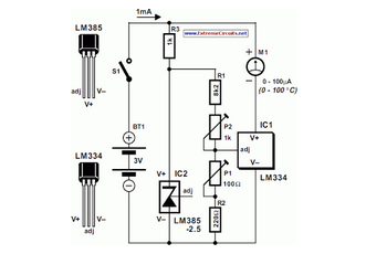
The circuit of the Celsius thermometer in the diagram is based on the well-known Type LM334 from National Semiconductor. This integrated circuit (IC) serves as a sensor that provides temperature readings. The Celsius thermometer circuit utilizes the LM334 integrated circuit,...
Amplifying the output from the iPod's headphone jack is necessary because the signal is insufficient for the chip to respond adequately. This situation arises from research conducted on three different chips. The LM3914 is a linearly calibrated device, meaning...
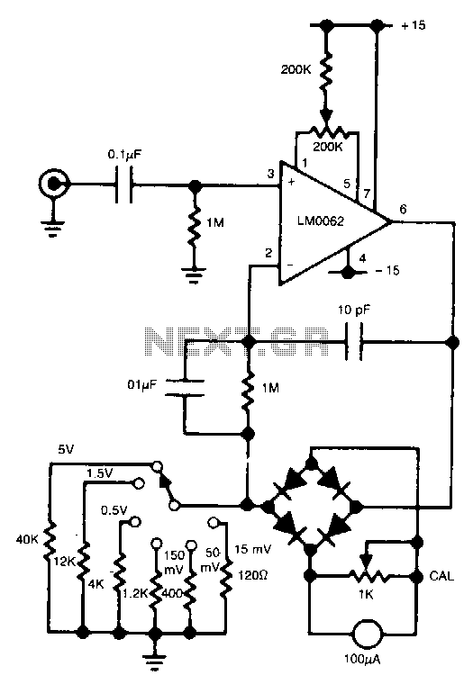
In this circuit, a diode bridge is utilized as a meter rectifier. The offset voltage is compensated for by the operational amplifier, as the bridge is part of the feedback network. The circuit employs a diode bridge rectifier, which consists...
This circuit is a series-FET Voltmeter known as FETVM. The FETVM is designed to replace the function of a vacuum tube voltmeter (VTVM) while simultaneously providing a means to clean the appliance cord. Additionally, the drift rate of this...
This circuit generates a readout for a digital tachometer. IC9 functions as a 3-digit LED display driver, counter, and latch. IC8 operates the common cathode LEDs, which are activated by transistors Q1, Q2, and Q3. Refer to page 268,...
The input stage of this voltmeter circuit utilizes an operational amplifier and diode feedback to create a linear peak value rectifier circuit. A partial pressure isolation through resistors R1 and R2 directs the signal to a dual multi-channel BCD...