
DIGITAL TACHOMETER COUNTER
The described circuit serves the purpose of displaying rotational speed in a digital format through a tachometer. The primary component, IC9, is responsible for driving a 3-digit LED display, which allows for the visualization of the measured RPM (Revolutions Per Minute). It integrates functionalities of a counter and a latch, enabling it to count pulses from a sensor that detects the rotational speed of a motor or other rotating machinery.
IC8 is utilized to drive the common cathode LED configuration. This configuration means that the cathodes of the LEDs are connected to ground, and the anodes are driven high by the display driver IC. The activation of the LEDs is controlled by transistors Q1, Q2, and Q3, which act as switches. When a pulse is detected by the counter, the corresponding transistor will turn on, allowing current to flow through the specific LED segment, thus illuminating it. This process is essential for displaying the correct digits on the LED screen.
For accurate functioning, the circuit must be calibrated to ensure that the pulse count corresponds correctly to the actual RPM being measured. The layout of the circuit should minimize noise and interference, which could affect the accuracy of the tachometer readings. Proper power supply decoupling and grounding techniques should be employed to ensure stable operation.
Referencing page 268, Fig. 46-5 provides additional insights into the schematic and layout of the project, illustrating how the components interconnect and function together to achieve the desired tachometer readout.This circuit produces a readout for the digital tachometer circuit.IC9 is a 3-digit LED display driver,counter,and latch?IC8 drives the common?cathode LEDs,which are enabled by Q1,Q2,and Q3.See page 268?Fig.46-5 for the matching project?.. 🔗 External reference
Related Circuits
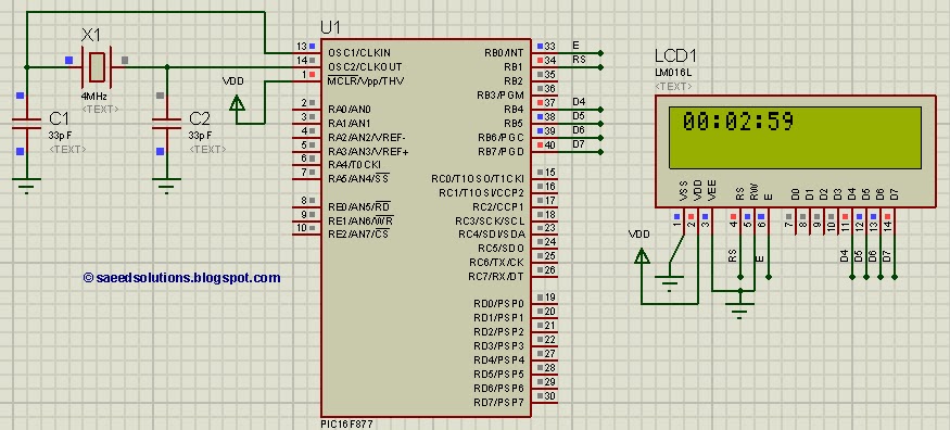
This tutorial on the PIC16F877 microcontroller addresses the question, "How to implement a digital clock using the PIC16F877?" The use of the PIC16 simulator (Proteus) is included. The PIC16F877 microcontroller is a versatile and widely used component in embedded systems,...
This digital dice circuit is designed to display numbers effectively. When the spin switch is turned off, it converts the input into a binary format using a diode matrix composed of diodes D1 to D9 (1N4148 or 1N914). This...
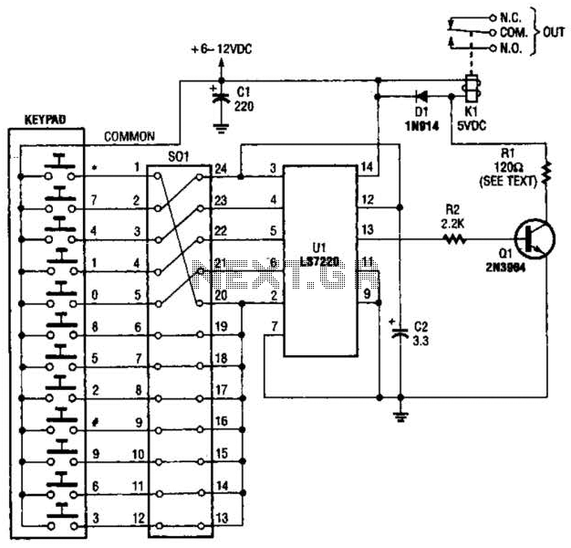
A block pinout diagram of the LS7220 keyless-lock IC is presented. The keypad must provide each key with a contact to a common connection. In this instance, the common connection is linked to the positive supply rail, allowing a...
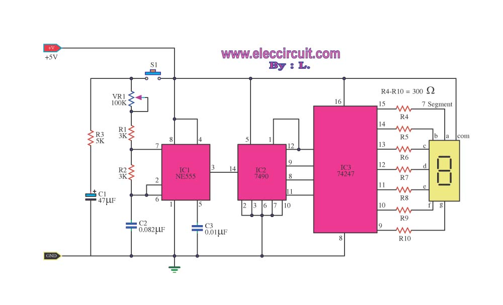
The digital scoreboard circuit is designed to display numerical values ranging from 0 to 9 on a common anode 7-segment display. The circuit employs a 7-segment driver integrated circuit (IC), specifically the 74LS47 or 74LS247. A 555 timer IC...
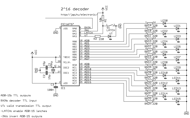
This encoder can transmit the state of up to 16 TTL digital inputs using an RF or infrared transmitter. When enabled, the included modulator automatically generates the 38kHz IR carrier. Containing a PIC microcontroller, the circuit is very flexible....
Power the frequency counter and adjust the coarse (top pot) and fine (bottom pot) controls to display zero frequency. Turn the pots counter-clockwise to achieve a zero reading. Occasionally, the counter may show only squares without digits. If this...