
Filament Light Dimmer Circuit
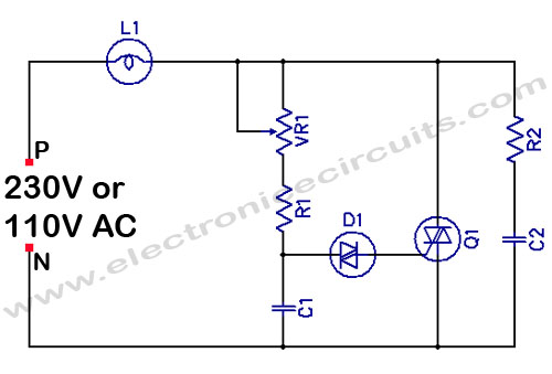
The filament light dimmer circuit utilizes a TRIAC to control the power delivered to incandescent lamps. The primary components include a TRIAC, a diac, resistors, and capacitors arranged to form a phase control circuit. The TRIAC acts as a switch that regulates the amount of current flowing to the lamp, allowing for a dimming effect.
When the circuit is powered, the diac remains non-conductive until the voltage across it reaches a certain threshold. Once this threshold is exceeded, the diac conducts, triggering the TRIAC. The timing of the TRIAC's conduction is controlled by the RC timing network, which determines at which point in the AC cycle the TRIAC will turn on. By adjusting the resistance or capacitance in this network, the phase angle at which the TRIAC begins to conduct can be varied, thus controlling the brightness of the lamp.
This circuit is suitable for applications where dimming capabilities are desired, such as in residential lighting or decorative fixtures. It is essential to ensure that the TRIAC is rated for the appropriate load current and voltage, and that adequate heat sinking is provided to dissipate any heat generated during operation. Additionally, proper isolation and safety measures should be implemented to prevent electrical hazards.
The design is straightforward and can be implemented on a PCB or a breadboard for prototyping. Careful attention should be paid to component placement to minimize noise and interference, ensuring stable operation of the dimmer circuit.Filament Light Dimmer Circuit This simple triac dimmer can be used to control incandescent filament lamps up to 200W. The circuit operates on.. 🔗 External reference
Related Circuits
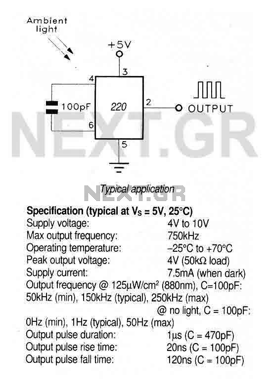
A large area photodiode and current-to-frequency converter integrated into a clear plastic 8-pin DIL package. The output generates a pulse train whose frequency is directly proportional to the light intensity. It is CMOS compatible (a 3.3kΩ pulldown resistor is...
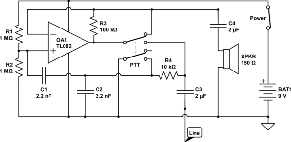
The circuit operates in receive mode, with the Push-To-Talk (PTT) switch enabling transmit mode. The speaker functions as both a microphone and a speaker. Most systems observed utilize a rocking armature transducer for the speaker. There is no base...

This design circuit is a tone control circuit that utilizes the popular Baxandall configuration, a straightforward circuit layout that allows for continuous boost and cut control. The circuit is inexpensive to construct and is frequently implemented in commercial products....
The proximity detector detects the movement of PC board pieces as the wheel rotates, generating an output signal with a clear transition between high and low voltage levels, making it suitable for triggering counting or processing circuits. Following this...
The LED blinks as expected, then pauses for an indefinite duration, flashes again a different number of times, and turns off again, displaying no discernible cyclic behavior. It activates without any external input, indicating that there is likely no...

This design circuit functions to filter out interference signals, ensuring that the signal received from a Morse code station is distinct. The circuit utilizes the earliest mode of radio communications, which employs Morse Code on a continuous wave carrier...
Warning: include(partials/cookie-banner.php): Failed to open stream: Permission denied in /var/www/html/nextgr/view-circuit.php on line 713
Warning: include(): Failed opening 'partials/cookie-banner.php' for inclusion (include_path='.:/usr/share/php') in /var/www/html/nextgr/view-circuit.php on line 713