microcontroller Seemingly unstable basic PIC18F2550 circuit
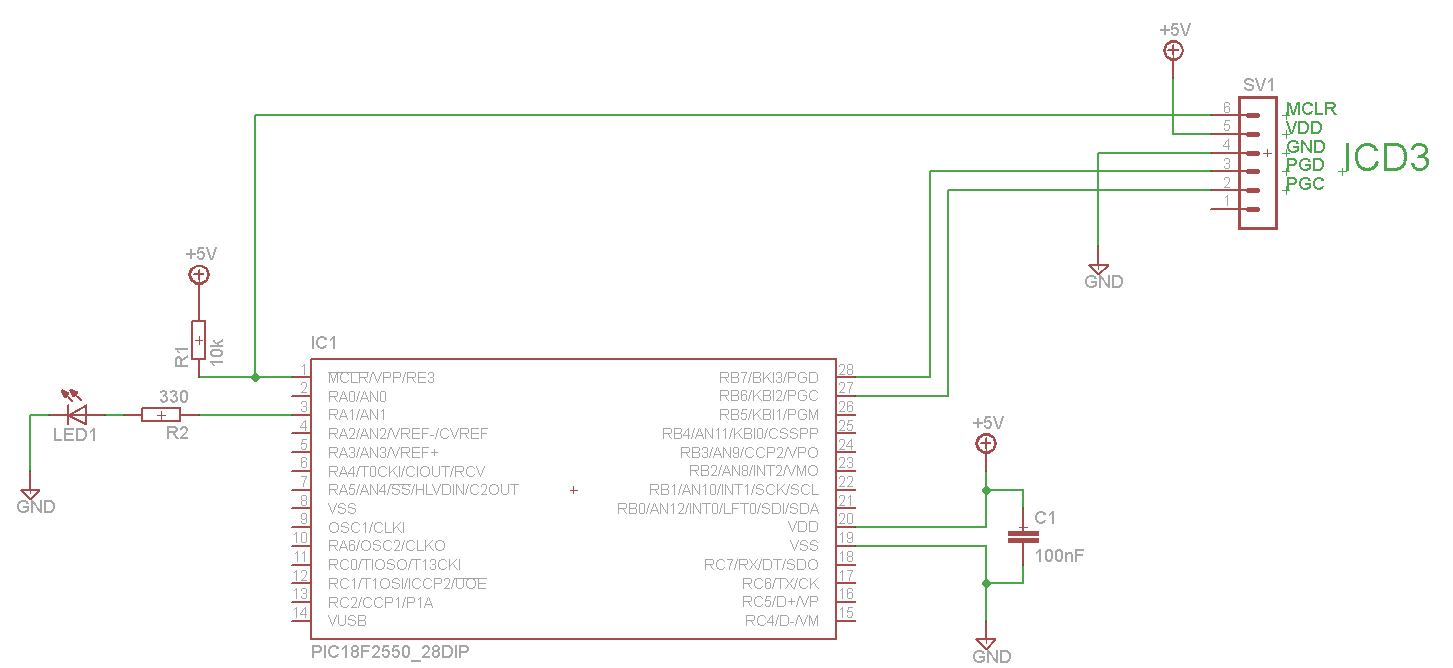
The LED blinks as expected, then pauses for an indefinite duration, flashes again a different number of times, and turns off again, displaying no discernible cyclic behavior. It activates without any external input, indicating that there is likely no loose connection. It has been noted that the second Vss pin is not grounded in the schematic, but grounding it did not resolve the circuit issue. There is a question regarding whether Vusb not being grounded could be a factor, although it was assumed that this would only impact USB functionality.
#include <stdio.h>
#include <stdlib.h>
#include <p18f2550.h>
#include <delays.h>
#pragma config FOSC = INTOSCIO_EC
#pragma config WDT = OFF
void main() {
TRISAbits.TRISA1 = 0; // Set RA1 as output
LATAbits.LATA1 = 1; // Set RA1 as HIGH
while (1) {
LATAbits.LATA1 = ~LATAbits.LATA1; // Toggle LED pin
Delay10KTCYx(25); // Delay
}
The described circuit involves an LED connected to a microcontroller (specifically the PIC18F2550) that is programmed to toggle its state at regular intervals. The microcontroller is configured to use an internal oscillator and has the watchdog timer disabled. The LED is connected to pin RA1, which is set as an output.
The main loop of the program toggles the state of the LED by using the bitwise NOT operation on the LATAbits.LATA1 register. This effectively turns the LED on and off, creating a blinking effect. The delay function, Delay10KTCYx(25), introduces a pause between toggles, allowing for a visible blink rate.
Issues noted in the circuit operation may stem from grounding problems. The second Vss pin not being grounded could lead to erratic behavior in the microcontroller, impacting its ability to process signals correctly. Similarly, if Vusb is not grounded, it might cause instability in the circuit, even if it is assumed that this would primarily affect USB operations. Proper grounding of all relevant pins is crucial for reliable circuit performance, and any discrepancies in the schematic should be addressed to ensure consistent operation of the LED blinking function.The LED blinks as intended, then stops for an arbitrary time, flashes again a different number of times, off again etc. There doesn`t seem to be any cyclic behaviour to it. It starts working without any external input (i. e. nudging it) so doesn`t seem like a loose connection either. I realise the second Vss pin isn`t grounded in the schematic, but this didn`t help the circuit either when I tried it.
Could it be because Vusb isn`t grounded I would have thought this would only affect USB operation. #include #include #include #include #pragma config FOSC = INTOSCIO_EC #pragma config WDT = OFF void main() { TRISAbits. TRISA1 = 0; // Set RA1 as output LATAbits. LATA1 = 1; // Set RA1 as HIGH while (1) { LATAbits. LATA1 = ~LATAbits. LATA1; // Toggle LED pin Delay10KTCYx(25); // Delay } } 🔗 External reference
#include <stdio.h>
#include <stdlib.h>
#include <p18f2550.h>
#include <delays.h>
#pragma config FOSC = INTOSCIO_EC
#pragma config WDT = OFF
void main() {
TRISAbits.TRISA1 = 0; // Set RA1 as output
LATAbits.LATA1 = 1; // Set RA1 as HIGH
while (1) {
LATAbits.LATA1 = ~LATAbits.LATA1; // Toggle LED pin
Delay10KTCYx(25); // Delay
}
The described circuit involves an LED connected to a microcontroller (specifically the PIC18F2550) that is programmed to toggle its state at regular intervals. The microcontroller is configured to use an internal oscillator and has the watchdog timer disabled. The LED is connected to pin RA1, which is set as an output.
The main loop of the program toggles the state of the LED by using the bitwise NOT operation on the LATAbits.LATA1 register. This effectively turns the LED on and off, creating a blinking effect. The delay function, Delay10KTCYx(25), introduces a pause between toggles, allowing for a visible blink rate.
Issues noted in the circuit operation may stem from grounding problems. The second Vss pin not being grounded could lead to erratic behavior in the microcontroller, impacting its ability to process signals correctly. Similarly, if Vusb is not grounded, it might cause instability in the circuit, even if it is assumed that this would primarily affect USB operations. Proper grounding of all relevant pins is crucial for reliable circuit performance, and any discrepancies in the schematic should be addressed to ensure consistent operation of the LED blinking function.The LED blinks as intended, then stops for an arbitrary time, flashes again a different number of times, off again etc. There doesn`t seem to be any cyclic behaviour to it. It starts working without any external input (i. e. nudging it) so doesn`t seem like a loose connection either. I realise the second Vss pin isn`t grounded in the schematic, but this didn`t help the circuit either when I tried it.
Could it be because Vusb isn`t grounded I would have thought this would only affect USB operation. #include

