
Filter
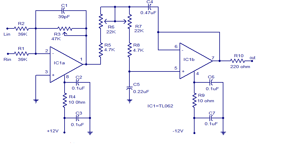
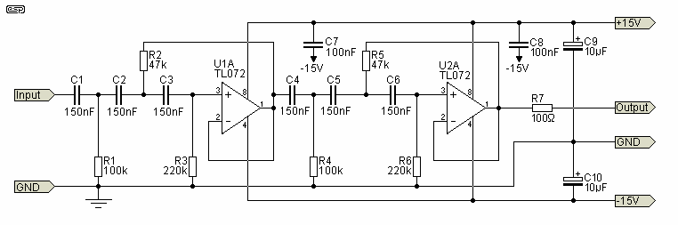
The low-pass filter circuit designed for subwoofer applications employs the TL062 operational amplifier, which is advantageous due to its low noise and high fidelity characteristics. The circuit begins with the first op-amp (IC1a) configured in an inverting amplifier configuration, where the audio signals from the left and right channels are mixed. The gain of this stage is adjustable via the potentiometer R3, allowing for fine-tuning of the output level to cater to specific audio requirements.
Following the mixing stage, the output is fed into a filter network composed of resistors R5, R6, R7, R8 and capacitors C4, C5. This network is essential for attenuating high-frequency signals, ensuring that only the desired low-frequency components are passed through to the second op-amp. The choice of resistor and capacitor values in the filter network will determine the cutoff frequency of the low-pass filter, which is critical for optimal subwoofer performance.
The second op-amp (IC1b) is configured as a buffer to provide impedance matching and drive capability for the filtered output signal. This configuration prevents loading effects on the previous stage and ensures that the signal remains intact for further processing or amplification. The output from this buffer stage is made available at pin 7 of the TL062, allowing for easy integration with subsequent audio processing stages or amplification circuits.
Overall, this low-pass filter circuit offers a robust solution for subwoofer applications, leveraging the capabilities of the TL062 op-amp to achieve high-quality audio performance with adjustable gain and effective filtering of unwanted frequencies.Many low pass filter circuits for subwoofer are given here and this can be simply another one. The circuit given here using the opamp TL062 from ST Micro electronics. TL062 is twin high input impedance J-FET opamp that has very low power consumption and high slew rate. The opamp has wonderful audio characteristics and is extremely appropriate for this circuit. Out of the 2 opamps within TLC062, 1st one is wired because the mixer cum pre amplifier stage. The left and right channel are connected to the inverting input of IC1a for mixing. The gain of 1st stage will be adjusted using POT R3. The output of the first stage is connected to the input of second stage through the filter network comprising of parts R5, R6, R7, R8, C4 and C5. The second opamp (IC1b) is a buffer and also the filtered output is offered at the pin 7 of the TLC062.
🔗 External reference
Related Circuits
This circuit allows frequencies in the range of 300 Hz to 3.1 kHz, which are typical in human speech, to pass through. It is composed of cascaded high-pass and low-pass filters that together create a complete band-pass filter. One...
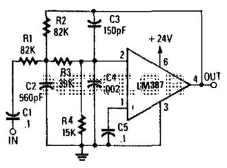
Designed to produce a 12-dB/octave roll-off above the 10-kHz cutoff frequency, this low-pass active filter will help reduce needle scratch on records. It utilizes an LM387 low-noise amplifier integrated circuit (IC). The low-pass active filter described is engineered to attenuate...
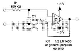
This simple filter utilizes an RC section as the filter element, incorporating a voltage follower to manage other frequencies. The -3 dB point is calculated as 1/(6.28 * RXCV), resulting in a response that drops 6 dB per octave...
The circuit shown is completely conventional. The Q of the filters has been optimized to allow a higher input impedance than would otherwise be possible, with the final Q of the two filters being almost exactly 0.707 (i.e., a...
This project involves the design of an air-filter sensor intended for use in home heating and cooling systems. The project encompasses conceptual design, analysis, implementation, testing, and modifications. Initially, the study focuses on comparing air quality and power consumption...
This circuit is taken from the Progressive Communications Receiver in most of the recent ARRL Handbooks. Values for the 40 meter band are shown. If you want the ultimate in a bandpass filter for 40 or 20 meters, check...