
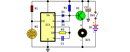
Fire activated alarm

The fire alarm circuit is designed to detect smoke and alert users through an audible signal. The primary components include a light-emitting diode (LED) bulb, a light-dependent resistor (LDR), a transistor, a chip-on-board (COB) sound module, an audio amplifier (IC TDA 2002), and a variable resistor (VR1) for sensitivity adjustment.
In operation, the circuit monitors the ambient light conditions between the LED bulb and the LDR. Under normal conditions, the LED emits light that falls on the LDR, maintaining a low resistance value. When smoke enters the detection area, it scatters the light, reducing the intensity that reaches the LDR. The decrease in light intensity causes the resistance of the LDR to increase, which in turn raises the voltage at the base of the transistor. This triggers the transistor, allowing current to flow to the COB, which produces the alert sound.
The COB module can be selected based on the desired sound output, providing flexibility for different applications. The audio amplifier, utilizing the TDA 2002 IC, enhances the signal from the COB to ensure that the alarm is loud enough to be heard in various environments.
Sensitivity adjustments are critical for the circuit's performance. By altering the distance between the bulb and the LDR as well as tweaking the preset resistor VR1, users can fine-tune the circuit to respond appropriately to smoke levels. This customization allows for effective detection in different settings, accommodating variations in smoke density and environmental conditions.
Incorporating an ON/OFF switch allows users to activate or deactivate the circuit as needed, providing control over the system's operation. This feature is particularly useful during maintenance or when the alarm is not required, ensuring that the circuit can be easily managed. Overall, this smoke detection circuit provides a reliable solution for fire safety, leveraging simple electronic components to deliver an effective warning system.This circuit warns the user against fire accidents. It relies on the smoke that is produced in the event of a fire. When this smoke passes between a bulb and an LDR, the amount of light falling on the LDR decreases. This causes the resistance of LDR to increase and the voltage at the base of the transistor is pulled high due to which the supply to the COB (chip-on-board) is completed. Different COBs are available in the market to generate different sounds. The choice of the COB depends on the user. The signal generated by COB is amplified by an audio amplifier. In this circuit, the audio power amplifier is wired around IC TDA 2002. The sensitivity of the circuit depends on the distance between bulb and LDR as well as setting of preset VR1. Thus by placing the bulb and the LDR at appropriate distances, one may vary preset VR1 to get optimum sensitivity.
An ON/OFF switch is suggested to turn the circuit on and off as desirable. 🔗 External reference
Related Circuits

In the presence of combustible gas, the conductance of the TGS308 gas sensor increases, causing the voltage at the potentiometer RP1 slide point to rise from a normal 3V RMS to 20V. This elevated voltage is applied to transistor...

The automatic alarm circuit comprises a DTMF automatic dialing system, a password control circuit, a voice detection and alarm circuit, a telephone interface circuit, a power supply circuit, and a keyboard display circuit. The automatic dial-up alarm utilizes the...
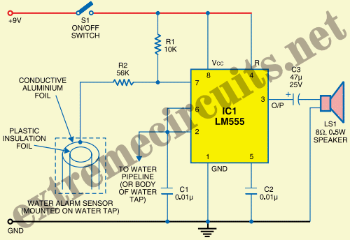
The State Jal Boards provide water for a limited duration each day. The timing of water supply is determined by the management, and the public is not informed of this schedule. The operation of State Jal Boards typically involves a...

Have you ever accidentally left your front door ajar and had a pet escape? Here is a smart solution to this problem. The circuit is relatively simple but serves as a great example of using a compact circuit to...

The circuit for the photoelectric switch S1 functions as a control switch for the luggage room light. In its closed operating state, the voltage is positive. If S2 is closed, irrespective of the state of S1, the output terminal...
This circuit is housed in a compact enclosure and is positioned within the refrigerator, either near the lamp or at the door opening. When the refrigerator door is closed, the interior remains dark, causing the photoresistor R2 to exhibit...