
Car or room timer alarm circuit diagram
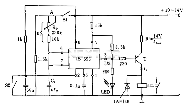
The described circuit utilizes a photoelectric switch system that effectively manages lighting and alarm functionalities in a luggage room environment. The primary components include a photoelectric switch S1, a normally open contact switch S2, a capacitor Cl, a resistor Rl, a potentiometer RP for time adjustment, a transistor, and a relay.
The operation begins with the photoelectric switch S1 detecting the presence of an object or an open door, which leads to its closed state. In this condition, the circuit allows for a positive voltage to be present. The normally open contact switch S2 plays a critical role in the system's operation. When S2 is closed, it ensures that the output voltage U3 remains high, which keeps the transistor in an 'on' state. Consequently, the relay does not engage, and the LED remains off, indicating that the system is in a standby mode.
As the door opens, S1 closes, allowing capacitor Cl to charge slowly through resistor Rl. The charging time can be adjusted using potentiometer RP, which can be set to any value up to 60 seconds. This feature allows for flexibility in determining how long the system will wait before triggering the alarm. Once the capacitor Cl reaches a specific voltage threshold, the output voltage U3 drops suddenly, which activates the relay. This action signifies that an alarm condition has been met, prompting the alarm system to engage.
Furthermore, if the alarm is active and S2 is subsequently closed, the output voltage U3 remains high, which results in the relay being released. This functionality ensures that the system can reset itself under certain conditions, providing an efficient and responsive control mechanism for the luggage room light and alarm system.
Overall, this circuit design effectively integrates light control and alarm functionalities, ensuring safety and operational efficiency in environments requiring monitoring of access points. The adjustable timing feature enhances the system's versatility, allowing it to be tailored to specific operational requirements. Circuit photoelectric switch S1 is gated or luggage room light control switch. A point is in its closed operating voltage is positive. If S2 is closed, regardless of whether or not S1 is closed, the output terminal voltage U3 are high, transistor is turned on, the relay does not pull, the light emitting diode LED is not illuminated. S2 is a normally open contact, if S1 is closed (door open), the Cl slowly charged through Rl. At a certain time (adjustable by potentiometer RP can not exceed 60s) inside, U3 suddenly goes low, then the relay is turned on, the alarm is working.
If the alarm S2 is closed, and the U3 is high, the relay releases.
Related Circuits
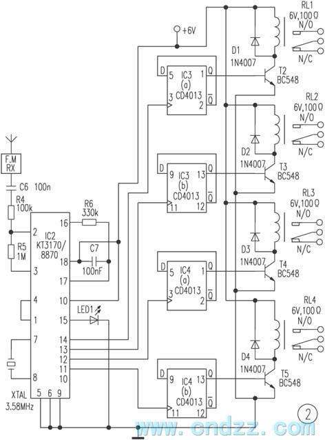
The remote control transmitter consists of a DTMF generator and an FM transmitter circuit. A UM91214B phone-specific integrated circuit (IC) is utilized to generate the DTMF signal, with a 3V power supply provided by a 3V zener diode (D1)....

A simple technique for measuring frequencies across a wide range with acceptable accuracy limits using a PC is presented. This method follows the basic principle of measuring low frequencies, where the period of a complete wave is measured and...
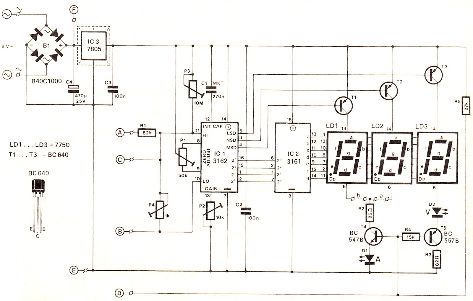
This voltage/current (V/I) display module is well-suited for integration into an existing DC power supply, providing precise readings of the set voltage or the current consumption of the load. The voltage measurement range features a decimal point indicator (LD3),...
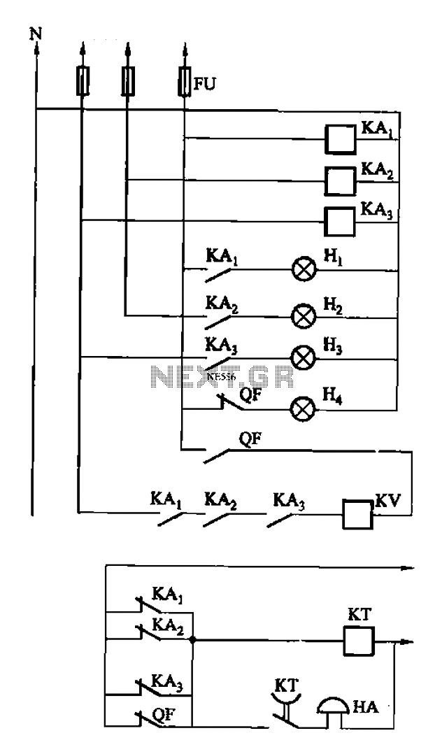
The circuit features intermediate relays KAi, KA2, and KA3, which are connected to the outlet end of the low-voltage circuit breakers. An alarm circuit is linked to a backup power supply or a battery power supply. This configuration serves...
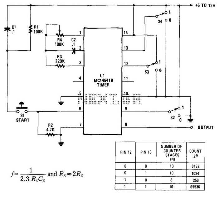
By utilizing an RC oscillator and a programmable divider, this counter can operate for extended periods. The interval oscillator functions at a frequency determined by specific component values: for instance, with R1 = 390 kΩ and C2 = 10...

A digital tachometer and speedometer utilizing a seven-segment display was initially attempted but not successfully implemented due to overcrowding of integrated circuits (ICs) and components. An LED tachometer was successfully constructed later, followed by the development of an LED...
Warning: include(partials/cookie-banner.php): Failed to open stream: Permission denied in /var/www/html/nextgr/view-circuit.php on line 713
Warning: include(): Failed opening 'partials/cookie-banner.php' for inclusion (include_path='.:/usr/share/php') in /var/www/html/nextgr/view-circuit.php on line 713