
Fishermans Dipper
The measuring resonant circuit, while actively operating, is loosely coupled to the resonant circuit of the dipper, meaning it is brought close to it. The dipper is tuned from the lowest to the highest frequency. When the dipper and the program under test resonate together, the program extracts energy from the dipper, resulting in a voltage drop at the indicator instrument. The pointer of the instrument "dips" clearly below the zero point, creating a "Dip," which is the origin of the name. In passive operation, as absorption frequency meters, the delivered RF from a module (e.g., VFO) can be determined by an inverted Dip, where the LED lights up at resonance. Another application in active operation includes using it as a signal generator, determining the periodic resonance of a radio frequency choke (RFC), and measuring the velocity factor of a cable. A small indicator instrument must fit inside a pharmacy box, or it can be replaced with another indicator. An LED is preferred due to its compact size compared to other solutions. In practical use, the Dip is clearly visible, eliminating doubts about whether the pointer moved or if hand tremors affected the reading. The circuit consists of an oscillator using FET VT1 (BF245C), with a resonant circuit formed by a variable capacitor and a plug coil. RF is uncoupled from this oscillator through a capacitor (8.2 pF), routed through a silicon diode in parallel, and amplified via a Darlington stage with transistors VT2/VT3 (BC547C) to drive the LED display. The brightness of the LED increases with higher RF voltage. The central component of the circuit is the Sub D socket, which powers the display module through a bridge connected to the plug coils, which also serve as measuring range switches. The pharmacy box requires specific recesses and holes to be drilled. The center hole is for the variable capacitor, while edge holes accommodate the LED. A trapezoidal recess for the Sub D socket is created by drilling small 1 mm holes along the desired shape and carefully removing the material with small shears. Additional holes are drilled for the "active-passive" switch and the sensitivity adjuster. The cover of the box is modified on the rear side, ensuring it closes correctly without interference from the switch or Sub D socket. A suitable piece of universal printed circuit board (preferably strip PCB) is prepared to cover the bottom of the box, with appropriate holes for the variable capacitor and LED. This PCB is mounted upwards with conductive strips inside the box, providing mechanical stabilization. The Sub D socket and variable capacitor are then inserted with their connections. Remaining sections are fastened, and wiring begins based on the Sub D socket, starting from the lower series. For coil production, connector sockets for cable carriers (PVC pipes) of size PG16 (German gauge, 16 mm diameter) are used, with three small holes bored for winding wire. The coil is started from the "cold end."
The described circuit functions as a versatile RF measurement tool, capable of both active and passive operations. In active mode, it serves as a signal generator and frequency measurement device, utilizing the principles of resonance to determine the characteristics of various RF components. The use of a dipper allows for precise tuning, enabling the user to identify resonant frequencies effectively.
The oscillator circuit, built around the FET VT1, generates a stable RF signal, which is crucial for accurate measurements. The variable capacitor allows for fine-tuning of the resonant frequency, while the plug coil provides flexibility in measurement ranges. The Darlington transistor configuration enhances the output signal, driving the LED display that visually indicates the presence of resonance through its brightness.
The incorporation of a Sub D socket facilitates easy connection to external equipment, ensuring that the circuit can be integrated into larger measurement setups or used standalone. The design emphasizes compactness and practicality, with the pharmacy box serving as a robust housing for the components. The careful arrangement of components and the thoughtful design of the PCB contribute to the overall functionality and reliability of the circuit.
In terms of assembly, the detailed instructions for drilling and fitting components into the pharmacy box ensure that users can replicate the design with precision. The use of PVC pipes for coil winding is a practical choice, allowing for easy modifications and ensuring that the coils can be produced efficiently. Overall, this circuit represents a well-thought-out approach to RF measurement, combining functionality with ease of use.With the active operation a measuring resonant circuit (program under test) is coupled loosely at the resonant circuit of the dippers, i. e. brought in its proximity. The dipper is tuned by the lowest to the highest frequency. If dipper and program under test are in resonance, then the program under test extracts energy from the dipper and it comes to a voltage drop at the indicator instrument.
The pointer of the instrument " dips " clearly the zero point against, it makes a " Dip ". therefore the name. In the passive operation as absorption frequency meters the delivered RF of a module (e. g. VFO) can be determined by an inverted Dip, i. e. the LED lights up with resonance. Further application type in the active operation is the use than signal generator, the determination of the periodic resonance of RFC (radio frequeny choke) and the determination velocity factor of an cable. Over this dipper in a pharmacy box to accommodate a very small indicator instrument must be available or however one replaces it by another indicator.
It offers itself an LED, in addition, a tone generator that its frequency as a function of the RF voltage which can be measured modifies is conceivable. First sceptically I decided for the LED, because she nevertheless bring along in relation to other solutions to few volumes.
In the practical operation I was then nevertheless surprised, as a Dip appears clearly. Also the question: " have itself does the pointer moved or I tremble with my hand " no more does not place itself with this inertialess display. The circuit consists of an oscillator with the FET VT1 (BF245C), whose resonant circuit from the variable capacitor and a plug coil is formed.
From this oscillator over a condenser (8. 2 pf) RF is uncoupled, brought with a silicon diode parallelly and over a Darlington stage with the transistors VT2/VT3 (BC547C) and the LED to the display. The more highly the RF voltage, the the bright LED. Central point of the circuit is the Sub d socket. Over a bridge at the plug coils the voltage for the display module is switched on. The plug coils serve measuring range switching. First into the pharmacist box the necessary recesses and holes are bored. In the center the drilling for the variable capacitor, something at the edge for the LED. At the page the recess for the Sub d socket is ripped out. Since this recess must be trapezoidal, one bores much small 1 mm of holes along the desired form and tries the material out carefully with small shears to rip.
Then the holes for the switch (" active - passive ") and the adjuster for sensitivity follow. The cover of the box is demoted to the rear side and must in the places, where it comes with the switch and the Sub d socket into contact something is left blank, so that it closes correctly. Then a piece of universal printed circuit board (best been suitable strip PCB) is made suitable, so that they provide the soil of the box covered and with appropriate holes for variable capacitor and LED.
This PCB is stuck upward with the conductive strips into the box. This serves at the same time the mechanical stabilization of the housing. Then the Sub d socket and the variable capacitor with the links are inserted toward Sub d socket. Afterwards all remaining sections become, into which fastens drillings. Now the wiring can begin on the basis of the Sub d socket, i. e. from their lower series. For the production of the coils connector sockets for cable carriers (PVC pipes) serve the size PG16 (German gauge, diameter 16 mm), which gives it on each building market. Into these PVC cases three small holes are bored for executing the winding wire. One begins the coil of the " cold end " ago to w 🔗 External reference
Related Circuits

The circuit consists of two fundamental components: the oscillator and the detector. The oscillator employs a Field Effect Transistor (FET) in a Colpitts configuration. The energy circulating within the oscillator's tank is coupled through capacitor C4 to the detector...
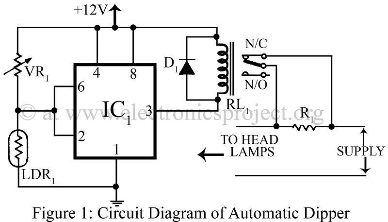
An automatic dipper for vehicles utilizing a timer IC NE555 and a light-dependent resistor (LDR) to control the headlight intensity of vehicles. This circuit diagram serves as a reference for various automobile projects. The automatic dipper circuit employs the NE555...