
Automatic Dipper for Vehicles using NE555
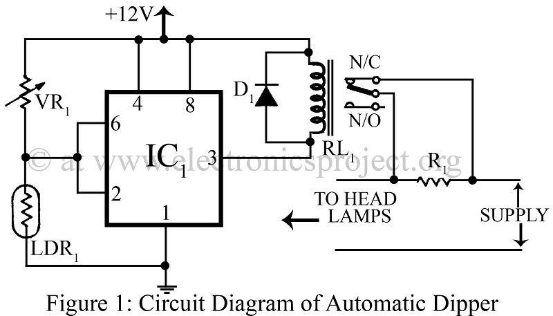
The automatic dipper circuit employs the NE555 timer IC configured in an astable mode to generate a pulse-width modulation (PWM) signal, which is instrumental in controlling the headlight intensity based on ambient light conditions. The LDR is used as a sensor to detect the level of surrounding light. When the ambient light falls below a certain threshold, the resistance of the LDR decreases, triggering the NE555 timer to activate the vehicle's headlights at a lower intensity.
The circuit typically includes a few key components: the NE555 timer, the LDR, resistors, capacitors, and a relay. The relay serves to switch the vehicle's headlights on and off or change their intensity based on the output from the NE555 timer.
In operation, the LDR continuously monitors the light levels. When it senses low light, the NE555 timer is activated, and the output pin of the timer sends a signal to the relay. The relay then engages, allowing current to flow to the headlights and dimming them as necessary. The timing components (resistors and capacitors) connected to the NE555 determine the sensitivity and response time of the circuit, allowing for customization based on the specific requirements of different vehicles.
This automatic dipper circuit enhances driving safety by ensuring that headlights are appropriately adjusted according to environmental conditions, thus preventing glare to oncoming drivers and improving visibility for the vehicle's operator.Automatic Dipper for Vehicles using timer IC NE555 and LDR use to dip the light of vehicles circuit diagram with description various automobile project. 🔗 External reference
Related Circuits
Upon purchasing the slave dial, it arrived without instructions, packaging, or additional details. The only visible markings, aside from decades of grime, were on the face (SMITH SECTRIC, ACELEC SYDNEY) and some markings on the bracket holding the mechanism...
Have you ever wanted to create a line-following robot but found infrared sensors too expensive? If you are located in the UK and have access to a Maplin store nearby, you can purchase infrared transmitters and receivers for just...
The charging circuit automatically stops when the battery is fully charged, allowing the emergency light to remain connected to the AC mains overnight without concern. The circuit consists of two main sections: the inverter and the charger. The inverter...
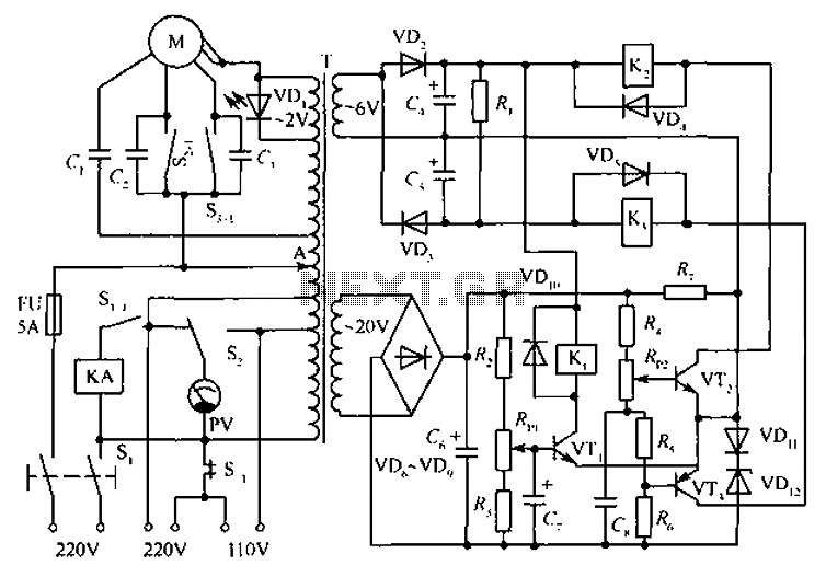
The circuit depicted in the figure includes an automatic voltage regulator (T) that maintains a constant output by utilizing a servo motor. The circuit features transistors VT1 and VT2 (3DK9), with a capacitance range of C (65 ~ 85)....
Introduction The design of off-line constant voltage, constant current (CVCC) power supplies using the NCP1014 for devices such as cell phones, hand tools, and similar battery chargers can present various challenges when low cost and circuit simplicity are required...
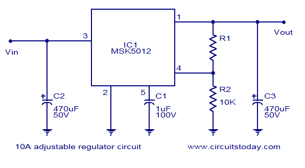
A reliable 10A adjustable voltage regulator based on the MSK5012, featuring an output voltage range of 1.3 to 30V. It is characterized by low ripple and high efficiency. The MSK5012 adjustable voltage regulator is designed for applications requiring a stable...
Warning: include(partials/cookie-banner.php): Failed to open stream: Permission denied in /var/www/html/nextgr/view-circuit.php on line 713
Warning: include(): Failed opening 'partials/cookie-banner.php' for inclusion (include_path='.:/usr/share/php') in /var/www/html/nextgr/view-circuit.php on line 713