
flashing lights

The astable multivibrator circuit functions as a basic oscillator that generates a square wave output, which is utilized for blinking the LEDs. The two transistors, TR1 and TR2, are configured in a feedback loop that allows them to alternately turn on and off. This self-sustaining operation is facilitated by the charging and discharging of the capacitors C1 and C2, which control the timing of the switching.
The resistors R1 and R2 are crucial in determining the charge time of capacitor C1, while R3 and R4 perform a similar function for capacitor C2. The values of these resistors, along with the capacitance of the capacitors, will dictate the frequency of the blinking LEDs. By selecting different resistor and capacitor values, the blinking rate can be adjusted to suit various applications, such as decorative lighting or visual indicators.
The circuit's design is relatively simple, making it an excellent project for electronics students. The inclusion of a 9V battery as a power source provides sufficient voltage for the transistors to operate effectively. Additionally, the use of LEDs ensures low power consumption while still producing a visually appealing light output.
In summary, the astable multivibrator circuit serves as a foundational project for understanding basic electronic principles, including oscillation, timing, and the use of active and passive components in circuit design. The availability of a kit simplifies the assembly process, allowing students to focus on learning and experimentation.The flashing LED light circuit and kit shown above is known as an astable multi-vibrator. The circuit diagram of the Flashing Lights is shown above. It consists of two transistors (TR1 & TR2), two electrolytic capacitors (C1 & C2), two lights or LED`s (L1 & L2), and four resistors (R1 to R4). When a 9V battery is connected to the circuit the trans istors TR1 and TR2 start to switch on and off in turn causing the LED`s to emit pulses of light. The circuit oscillates and the LED lights begin blinking alternately and continuously. To understand how the circuit oscillates we must consider the voltage variations across the capacitors C1 and C2. Consider the situation just before TR1 switches on. C1 has already charged up to 7 volts through R1. C2 is charging through R3 and when the voltage reaches 0. 6 volts TR1 turns on. The collector of TR1 and the positive end of C1 are pulled down to 0 volts which forces the negative end of C1 to -7 volts.
This has the immediate effect of switching TR2 off. C1, however, is also connected to +9 volts through R2 and this causes C1 to charge in the opposite direction. The voltage at the negative end of C1 (the base of TR2) therefore starts to change from -7 volts and rise towards 9 volts.
However, as soon as the voltage reaches +0. 6 volts TR2 switches on and a charged-up C2 turns TR1 off. C2 now charges in the opposite direction through R3. The voltage at the negative end of C2 rises towards 9 volts and turns TR1 on when it reaches +0. 6 volts. The circuit is now back in its initial state and the cycle repeats itself. The combination of C1 and R2 determines the time TR2 is switched off, and similarly C2 and R3 determine the time TR1 is off. The values used in the circuit give an on-time (and off-time) of about 1/3 second. This is a blinking rate of 3 flashes per second. Fortunately, students who wish to build and experiment with this circuit need to make no effort to locate all the parts, because ApogeeKits offers this circuit as an electronic kit!
Flashing LED light kit assembly is required. 🔗 External reference
Related Circuits
The task involved testing the capacitive properties of food by connecting various edibles to an Arduino. This project, known as BeetBox, was developed by Scott Garner, a student at NYU-ITP, who designed an innovative musical instrument that uses beets...
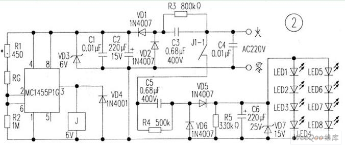
The circuit is depicted in Figure 1, while the electrical schematic diagram is presented in Figure 2. The AC voltage of 220V is reduced by components C3 and R3. The diodes VD1 and VD2 rectify the voltage, and capacitors...
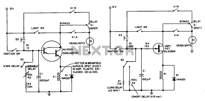
This circuit maintains the headlights of an automobile in an on state temporarily. It also ensures that the lights turn off automatically, even if the user forgets to switch them off manually. The shut-off delay is activated only when...
A 2003 Monte Carlo SS is experiencing issues with low idling, causing the engine to stall while driving or when parked. Additionally, the dashboard lights are malfunctioning; they occasionally activate for a brief moment before turning off again. There...
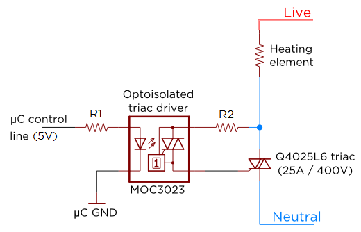
Several individuals have requested clarification on calculating resistor values for a triac circuit. This information may be beneficial for adapting the Sous Vader for custom builds. The circuit in question involves the resistor values R1 and R2 in an...
As a cyclist, there is a constant search for methods to enhance visibility during nighttime rides. The concept of the `NITE-RIDER` was developed to create a distinctive and attention-grabbing rear light for bicycles. This design features nine extra-bright LEDs...