
Flight Computer Assembly Instructions
Pins on chips are numbered counterclockwise. When viewing the top of a chip (with pins facing down), one end will have a notch or dot indicating pin number 1; orienting the chip with the notch up places pin 1 at the top left next to the edge with the notch. On this board, pin 1 connects to a square pad. It is advisable to determine the mounting method and drill mounting holes carefully to avoid damaging traces. Space has been allocated at both ends for this purpose. This document refers to the side of the board with the majority of components as the "upper" side and the opposite side as the "bottom" side. Identify the upper side of the board (labeled "Top") for all subsequent descriptions.
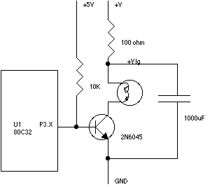
The Flight Computer V1.0 is designed to be a versatile and robust platform for various applications, utilizing a microprocessor architecture that supports a range of programming environments. The inclusion of an RS232 interface facilitates easy communication with external devices, making it suitable for integration into larger systems. The careful selection of components, including low-power options and socketed ROM, enhances both performance and ease of use. The layout and design considerations, such as the use of plated-through holes and fine traces, reflect an emphasis on reliability and manufacturability. Proper handling and assembly practices are critical to ensuring the longevity and functionality of the flight computer, particularly in environments where static sensitivity may be a concern. Overall, the Flight Computer V1.0 represents a comprehensive solution for hobbyists and professionals alike, offering a solid foundation for experimentation and development in embedded systems.Flight Computer V1. 0: B1 PC Board U1 80C32 microprocessor U2 27C256-12 32Kx8 ROM - 120nS U3 74HC373 U4 LM340T-5 5v regulator (might be a 7805 part) U5 43C256-15 32Kx8 RAM - 150nS U6 74HC00 T1-T4 2N6045 or 2N6044 darlington output transistors Y1 11MHz crystal S1 28-pin socket ROM socket R1 8k2 reset pullup R2 91 or 100 ohms charge reservoir fill ra te R3-R6 10k C1-C2 30 or 33pF C3 10uF C4 100uF power decoupling C5, C7 0. 01uF power decoupling C6 1000uF charge reservoir P1 6 pin connector main connector P2 10 pin header socket aux connector P3 3 pin header socket serial connector RS232 interface: U100 RS232 level converter - MAX232 or equiv. C100-C104 10uF capacitors P100 RS232 connector for your computer P101 small connector to match P3 above (included in the FC kit) Note that there should also be plugs to match all the connectors on the flight computer and a bag of pins for the plugs - they are very small so be careful you don`t lose them.
P1 is a 0. 156 (really 4mm) pitch molex connector available at many local electronic supply places - P2, P3 are 2mm DF3 connectors by Hirose Electric available from DigiKey. A number of the components - in particular the TO220 transistors and the crystal may have bent leads - straighten them out - they are intended to be placed vertically.
As usual you should observe care with static sensitive parts - only remove them from their tube just prior to using them and always gently ground yourself and your soldering iron tip prior to working with any parts. This board is designed to work with any of the 40-pin 8051/8031/8052/8032 variants of microprocessors - I`ve chosen the 80C32 mostly because it`s available and because it runs at a much lower power than the plain 8051/8031s that are more commonly available (15mA vs 160mA).
The PCB is double sided with plated through holes. It has rather fine traces - take great care not to bridge these use as little solder as you can - too much heat can cause them to lift or damage the thru-holes - try using a soldering iron with the finest tip you can find (1/32 for example). The 11mHz crystal can be replaced with a 12MHz one, or even a 16MHz one (if you have an 80C32-1) - but I`ve used 11MHz because the serial baud rates work out right with the simple timers.
In other words the supplied rom will stop working and you will have to provide your own. The ROM is socketed, I`ll provide already burnt ROMs containing a monitor, Basic and Forth that will talk to the serial port at 9600 baud - this monitor only works on 8032/8052 and variants (it uses the upper 128 bytes of on-board SRAM for a buffer). I`ve tried to write this document so that it has information for people with a whole range of experience building electronic gear - you may find parts of it too wordy - or too difficult or confusing - I`d appreciate feedback to help me make it better.
This page is rather long - I wanted to make it easy to print out a copy. Assembly can be done in 1/2 an hour, I suggest you take your time and go as slowly as possible. A component placement diagram is located after the assembly instructions below. Notes: pins on chips are numbered counter clockwise. If you look at the top of a chip (with the pins facing down one end will have a notch or a dot - the dot indicates pin number 1, the notch indicates the top, if you orient the chip with the notch up pin 1 is at the top left next to the edge with the notch. On this board pin 1 always goes into a square pad. Now is the time to decide how you are going to mount it and to drill mounting holes - do this with care and make sure not to damage any of the traces.
Space has been left at either end for this. Note that in this document we are going to refer to the side of the board that contains the bulk of the components as the "upper" side and the other side as the "bottom" side. Find the upper side of the board (labeled "Top") - for all the following descriptions the end co 🔗 External reference
Related Circuits
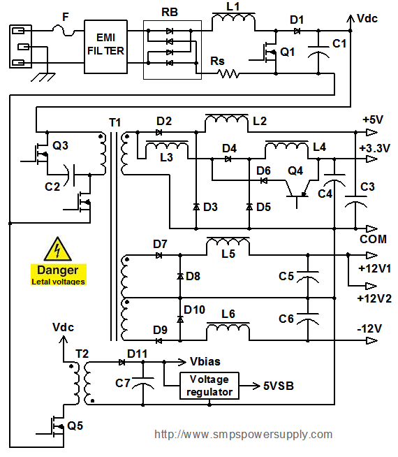
All electronic systems and equipment, regardless of their size or function, share a common requirement: a power supply unit (PSU) that converts input voltage into suitable voltage levels for their circuits. The most prevalent type of PSU today is...
This circuit is beneficial for connecting a computer to homemade robotics. It is straightforward to construct and operate, capable of controlling two DC motors of varying current and voltage ratings, contingent on the specifications of the relays used. Additionally,...
This circuitry facilitates the connection between the computer's Z RS-23 serial interface and the current ring circuitry. It converts the voltage signal of the transmission into a current signal of 20 mA, achieving a maximum speed of 1200 bits....
This circuit is a stable frequency counter with an accuracy of 5 significant digits. It operates within a frequency range of 0 to 30 MHz and has an input sensitivity greater than 100 mV. The probe connects to the...
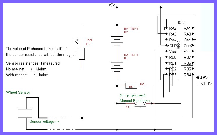
The printed circuit board (PCB) designed is large and provides ample space for modifications and additional components. However, to achieve the goal of integrating it into a real bicycle, its size presents challenges. Earlier discussions highlighted the importance of...
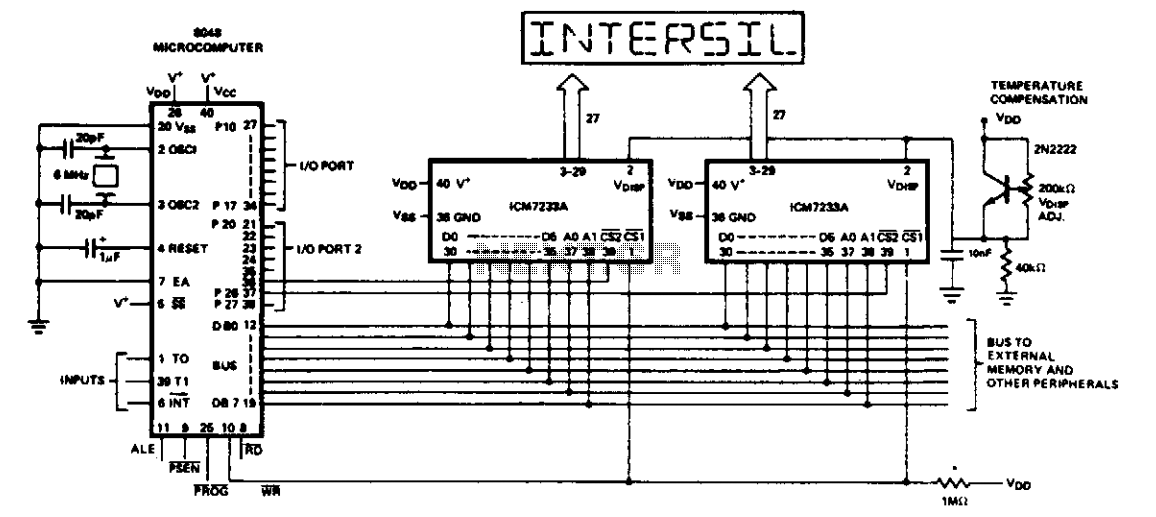
This is an 8048/IM80C48 microcomputer equipped with an 8-character, 16-segment ASCII triplex liquid crystal display. The two-bit character address is combined with the data and sent to the display driver under the control of the WR line. Port lines...
Warning: include(partials/cookie-banner.php): Failed to open stream: Permission denied in /var/www/html/nextgr/view-circuit.php on line 713
Warning: include(): Failed opening 'partials/cookie-banner.php' for inclusion (include_path='.:/usr/share/php') in /var/www/html/nextgr/view-circuit.php on line 713