
FM bug Spy transmitter circuit
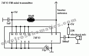
The FM spy transmitter is a compact device designed for covert audio transmission. The core component of this circuit is the 74F13 integrated circuit, which is a dual 4-input NAND gate. This IC is essential for generating the necessary frequency modulation (FM) signal. The circuit configuration typically involves the use of a coil, which acts as an inductor and is crucial for the RF transmission. The coil's inductance, in conjunction with the capacitor, determines the oscillation frequency of the transmitter.
The capacitor serves as a tuning element, allowing the circuit to stabilize and filter the signal, ensuring that the transmitted audio is clear and at the desired frequency. The additional component mentioned could refer to a resistor or another capacitor, which helps in biasing the circuit or adjusting the gain for optimal performance.
For assembly, the components should be connected according to a standard FM transmitter schematic, ensuring that the power supply is appropriate for the 74F13 IC. The circuit should be tested for functionality, with adjustments made to the coil and capacitor values to achieve the desired transmission range. Proper shielding and antenna design are also critical to enhance the performance and reduce interference.
This type of transmitter can be used in various applications, including surveillance and communication, making it a versatile tool for hobbyists and professionals alike. However, it is essential to comply with local regulations regarding radio frequency transmission to avoid legal issues.Take a look at this fm spy transmitter which can be used as a bug transmitter or as diy fm bug too. It uses a single IC 74F13, one coil, a capacitor, one t. 🔗 External reference
Related Circuits
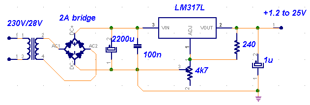
A truly timeless circuit. The LM317 is a versatile and highly efficient 1.2-37V voltage regulator that can provide up to 1.5A of current with a large heat sink. It is ideal for just about any application. This was the...
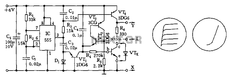
The transistor characteristic curve tracer circuit depicted in Figure 555 illustrates the characteristics of a transistor. It utilizes two voltages: a step wave applied to the base (b) to generate different base currents (Ib), and a sawtooth waveform at...

IC1 generates a pulse that modulates the 1000-Hz tone generated by IC2. This circuit can be used to generate warning or alert signals. The circuit described consists of two integrated circuits (ICs), where IC1 is responsible for generating a pulse...

The BA1404 FM stereo modulator IC includes all the necessary components to design a simple, high-efficiency stereo transmitter circuit. It features a stereo modulator that generates composite stereo signals, an FM modulator for creating FM signals, and an RF...
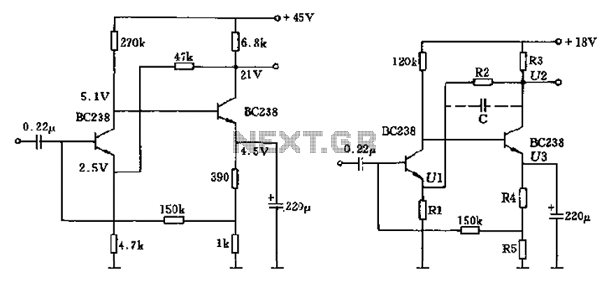
The circuit characteristic involves the elimination of external input resistors, which reduces the influence on the stabilization of the working point. It also employs two DC negative feedback loops. Additionally, the output from the second stage connects to the...
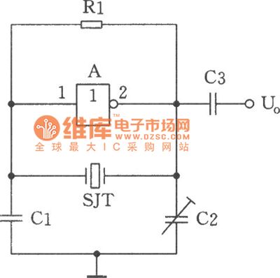
The image depicts a sine wave oscillator that consists of a quartz crystal (SJT) and gate A of the hex inverter IC CD4069. Compared to a standard RC phase-shift oscillator, the frequency stability of a crystal oscillator can achieve...
Warning: include(partials/cookie-banner.php): Failed to open stream: Permission denied in /var/www/html/nextgr/view-circuit.php on line 713
Warning: include(): Failed opening 'partials/cookie-banner.php' for inclusion (include_path='.:/usr/share/php') in /var/www/html/nextgr/view-circuit.php on line 713