
FM CB radio receiver circuit design using TCA440
The FM CB radio receiver circuit is designed for simplicity and efficiency, making it suitable for basic communication applications. The TCA440 integrated circuit serves as the core component, facilitating the reception and processing of frequency-modulated signals. Operating at an intermediate frequency of 455 kHz, the circuit effectively filters and demodulates incoming signals, ensuring clear audio output.
The input stage of the receiver incorporates a 27MF ceramic filter, which is essential for attenuating unwanted frequencies and enhancing the selectivity of the receiver. This filter plays a crucial role in defining the bandwidth of the received signal, thereby improving the overall performance of the receiver.
The use of a transformer for the intermediate frequency filter allows for a compact design. The transformer is set to provide a fixed gain of 40 dB for remote selection, which is advantageous in scenarios where signal strength may vary. This fixed gain configuration simplifies the design and reduces the need for manual adjustments.
For signal demodulation, a ceramic filter is employed, which efficiently extracts the audio information from the modulated carrier wave. This method of demodulation is known for its reliability and effectiveness in maintaining audio quality.
The circuit is powered by a 12 volts DC supply, which is a common voltage level for many electronic devices, making it convenient for integration into various applications. The audio amplification is handled by the LM386 integrated amplifier, which is well-regarded for its low power consumption and ability to drive small speakers or headphones. This amplifier ensures that the audio output is sufficiently loud and clear for user listening.
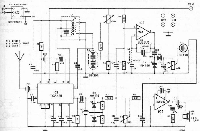
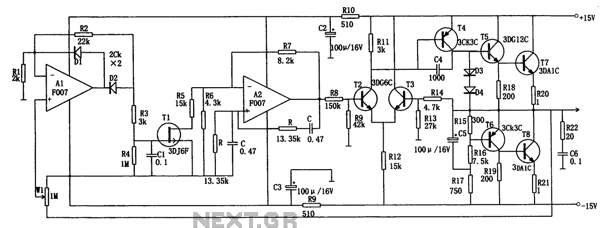
In summary, this FM CB radio receiver circuit is a straightforward design that leverages commonly available components to achieve reliable communication capabilities. Its architecture is optimized for ease of use and performance, making it an excellent choice for hobbyists and those looking to explore radio frequency technology.A very simple FM CB radio receiver can be designed using this electronic diagram below. This FM CB radio receiver circuit is designed using an TCA440 integrated circuit. The receiver works with a intermediate frequency of 455kHz. Input filter is 27MF ceramic type. Since the intermediate frequency filter transformer is used without adjustment, remo te selection is 40dB. Signal demodulation is also made with a ceramic filter. The entire assembly is powered with a voltage of 12 volts DC, the audio amplifier is realized with an LM386 integrated amplifier. 🔗 External reference
Related Circuits
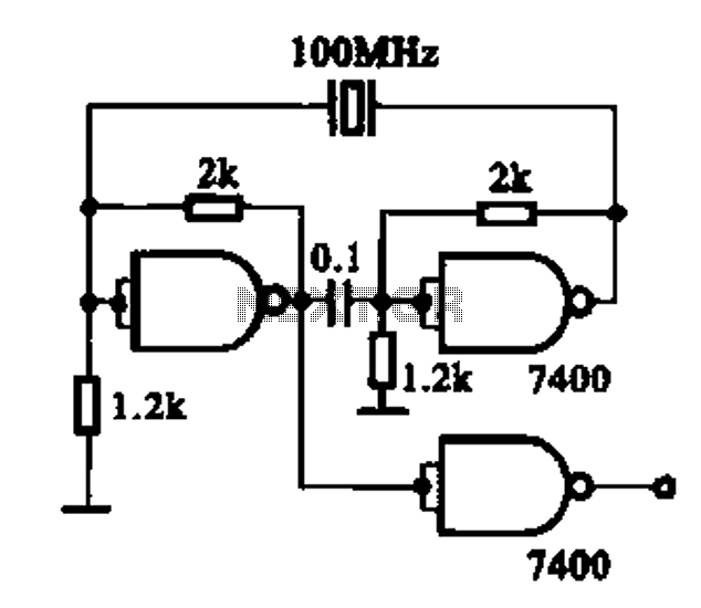
Crystal oscillator integrated circuits, specifically two diagrams of oscillator circuits with oscillation frequencies of 10 MHz and 20 MHz. Crystal oscillators are essential components in various electronic applications, providing stable frequency references for timing and synchronization purposes. The circuits presented...
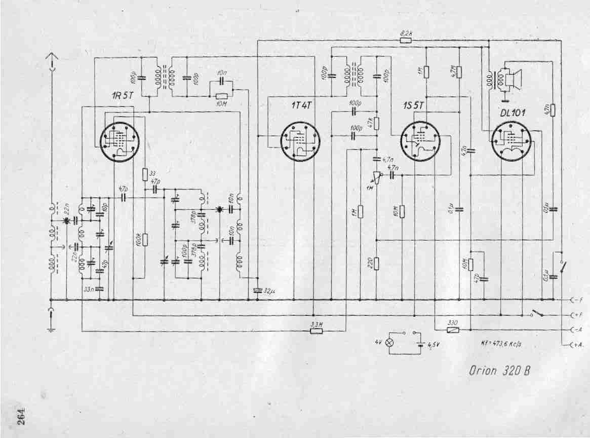
Create a repository of circuits and service data for vintage valve and transistor radios. While many resources are available online, they often come at a cost. The intention is to share circuits and manuals with others rather than profit...
SPI Integrated Circuit Bus, IC Buses, an IC, Chip-to-Chip Bus Serial Peripheral Interface, Integrated Circuit Bus types, and IC Bus Electrical Interface Descriptions. The Peripheral Interface (SPI) circuit is a. The Serial Peripheral Interface (SPI) is a synchronous serial communication...
The low-frequency signal generating circuit demonstrates excellent performance characterized by stable operation, high output power, and minimal waveform distortion. It serves as an ideal source for low-frequency measurement signals. The circuit includes an operational amplifier (A) with a feedback...

The automatic emergency light circuit has the following features: 1. When the mains supply (230V AC) is available, it charges a 12V battery up to 13.5V, after which the battery is disconnected from the charging section. 2. When the...
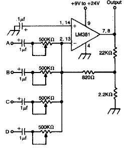
LM381 4-channel audio mixer circuit design project using a few common electronic parts. The LM381 audio mixer circuit is designed to combine audio signals from four separate channels into a single output. This circuit employs the LM381 integrated circuit, which...