
TTL integrated circuits made of a crystal oscillator

Crystal oscillators are essential components in various electronic applications, providing stable frequency references for timing and synchronization purposes. The circuits presented include two distinct configurations for crystal oscillators operating at frequencies of 10 MHz and 20 MHz, respectively.
The 10 MHz crystal oscillator circuit typically employs a fundamental mode crystal, which is connected in a feedback arrangement with an amplifier to maintain oscillation. The circuit may utilize a transistor or an operational amplifier as the active device. The crystal is connected in parallel with the feedback network, which can consist of resistors and capacitors that determine the oscillation frequency and stability. The output signal can be taken from the collector or emitter of the transistor, or from the output of the operational amplifier.
In contrast, the 20 MHz oscillator circuit may require a different approach to achieve the higher frequency. This circuit might utilize a similar feedback mechanism but could incorporate additional components such as a frequency multiplier or a more complex feedback network to ensure the oscillation frequency is accurately maintained. The choice of components, including the type of crystal, is crucial for achieving the desired frequency stability and low phase noise.
Both circuits share common characteristics, such as the need for proper power supply decoupling and grounding techniques to minimize noise and ensure reliable operation. Additionally, the layout of the circuit on a printed circuit board (PCB) should be designed to reduce parasitic capacitances and inductances that could affect the oscillator's performance.
These crystal oscillator circuits are widely used in applications ranging from clock generation in microcontrollers to frequency references in communication systems, highlighting their importance in modern electronics.Crystal oscillator integrated circuits, namely two 10 MHz and 20 MHz oscillation frequency diagram of the oscillator circuit.
Related Circuits
The multiplication operation required to generate a signal with a frequency equal to the difference of the input frequencies can be implemented in various ways. A multiplied signal typically appears when two signals are added and subsequently processed through...
A brief note explaining the process of substituting crystal and ceramic resonator clock circuits with silicon oscillators, while emphasizing the technical benefits these devices provide in microcontroller clock applications. Silicon oscillators serve as an effective alternative to traditional crystal and...
The world is full of xtal oscillators twiddled by digital designers lacking in the analog design knowledge necessary. Just look at all the PC real time clocks that lags or leads by several minutes per day. And they eat...
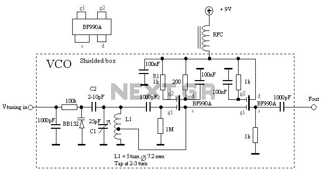
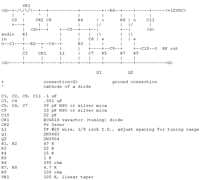
The VCO is based on a Hartley oscillator. The frequency is determined by L1 and capacitor C1. The tuning voltage will change the capacitance in the varactor BB132 which will change the oscillation frequency. The value of capacitor C2...
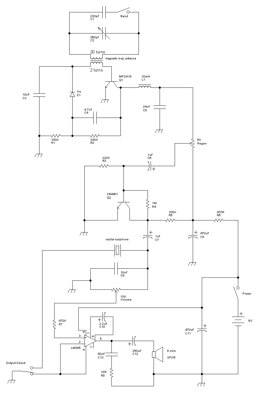
This receiver is a modification of Charles Wenzel's Two Transistor Reflex Radio. Instead of a ferrite AM loopstick antenna, a magnetic loop antenna is used, and an LM386 amplifier stage has been added to drive an 8-ohm speaker. A...
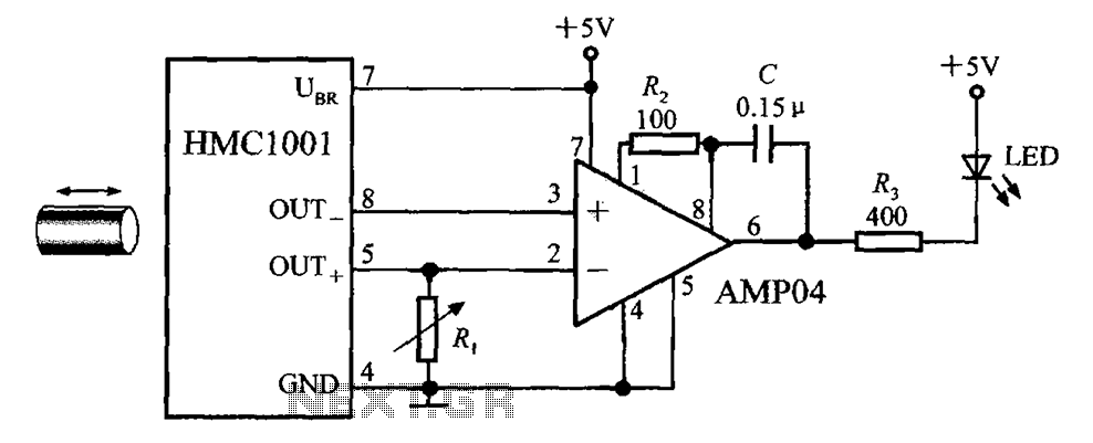
The circuit depicted in the figure includes the HMC1001 magnetic sensor, an operational amplifier (AMP04), and a light-emitting diode (LED), forming a proximity switch circuit. In this application, the operational amplifier functions as a comparator. When a magnet, approximately...