
FM (prm) optical transmitter
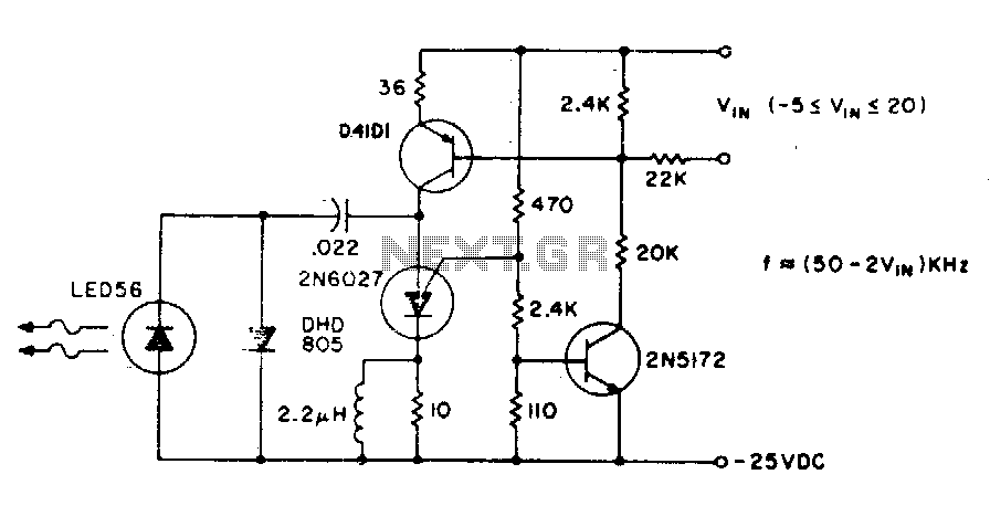
The described circuit is a frequency-modulated transmitter designed for applications requiring precise control over output characteristics. Operating at a fundamental frequency of 80 kHz, the circuit's performance is primarily dictated by the selected PUT capacitor arrangement. The modulation frequency is capped at 60 kHz, which is a critical parameter for ensuring signal integrity and minimizing distortion during transmission.
The relationship between the pulse repetition rate and the modulating voltage (Vin) indicates that the circuit is capable of dynamic adjustments based on input conditions. This feature allows for flexibility in various operating environments, making it suitable for applications that require adaptive modulation.
To mitigate stray light interference, the incorporation of optical components such as lenses or reflectors is essential. These components enhance the signal-to-noise ratio by directing the emitted infrared light more effectively and reducing ambient light interference.
For applications demanding higher output levels, two primary methods can be employed. The first method involves increasing the capacitance of the PUT capacitors, which not only boosts output but also lowers the operating frequency. The second method consists of selecting a higher power output IRED, such as the F5D1, which is designed to provide enhanced performance and efficiency in infrared transmission.
The circuit's average power consumption, which remains below 3 watts, indicates a design that is energy-efficient while still delivering adequate performance for its intended applications. This low power requirement is advantageous for battery-operated devices or systems where power availability is limited, thereby extending operational longevity without compromising functionality. Overall, this circuit design exemplifies a balance between performance, adaptability, and efficiency, suitable for a range of electronic applications.The basic circuit can be operated at 80 kHz and is limited by the PUT capacitor combination. 60 kHz is the maximum modulation frequency. The pulse repetition rate is a linear function of Vin, the modulating voltage. Lenses or reflectors minimizes stray light noise effects. Greater output can be obtained by using a larger capacitor, which also gives a lower operating frequency, or using a higher power output IRED such as the F5D1 Average power consumption of the transmitter circuit is less than 3 watts. 🔗 External reference
Related Circuits
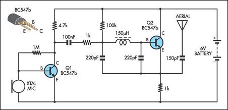
This low power FM transmitter is designed to utilize an input from another sound source and transmits on the commercial FM band. The transmitter is relatively powerful for its category. The first stage consists of an oscillator, which is...
This circuit utilizes a 74HC14 hex Schmitt trigger inverter as a square wave oscillator to drive a small signal transistor configured in a class C amplifier. The oscillator frequency can be set to a fixed value using a crystal...
This AM transmitter is designed for simplicity and ease of construction. It utilizes a single-winding inductor that is not tapped, eliminating the need for custom winding. A readily available RF choke, such as the Jaycar Cat LF-1536, can be...
The power output of most of these circuits is very low because no power amplifier stages were incorporated. The transmitter circuit described here has an extra RF power amplifier stage, after the oscillator stage, to raise the power output...
This application note provides a concise overview of power amplifier theory and presents simulation results that offer insights into the operation of the power amplifier across all of MAXIM's LFRF transmitters and transceivers. Power amplifiers are critical components in communication...

The following circuit is a power amplifier circuit for an FM transmitter with an output power of 30 watts. The power amplifier circuit utilizes a power transistor of type 2SC1946A. The FM transmitter operates with a 13.8-volt DC power...