
fm radio receiver
The described FM receiver circuit is a basic yet educational project for electronics enthusiasts. It operates on the principle of regenerative amplification, which enhances weak radio signals. The single transistor serves as the core amplification component, allowing the circuit to function without the complexity of integrated circuits. The use of variable capacitors is crucial for tuning, enabling the user to adjust the frequency range and optimize reception.
The circuit's design includes a tuning mechanism that can effectively capture signals from various sources, including FM radio stations and television audio, provided the signals are within a suitable strength range. However, the circuit's simplicity inherently limits its performance, making it more suitable for educational purposes than practical radio use. The regenerative nature of this receiver can lead to instability if not properly tuned, which can cause it to overload when exposed to strong signals.
In terms of construction, the layout of the circuit is essential. The placement of components on the veroboard should minimize stray capacitance, which can degrade performance. It is advisable to keep connections short and consider cutting traces to reduce unwanted capacitance effects. The circuit's schematic indicates a configuration that can utilize either two or four variable capacitors, which can be simplified by using a single variable capacitor with an appropriate capacitance range.
Overall, while this FM receiver circuit may not compete with commercially available radios in terms of performance, it provides a foundational understanding of radio frequency principles and circuit design. It serves as an introductory project for those looking to explore the world of electronics and radio communication.A very simple circuit for FM receiver, no IC required, and only a single transistor. I`m not sure whether this transistor works or not, I`m going to try this out. Have you guys seen this before It is a regenerative or super-regenerative simple radio receiver. Read about its problems in Google. It is too simple to be a real radio and is just a cheap child`s toy. Another guy was in this forum and for hundreds of posts about it he couldn`t make it work, except to pickup the sound from a powerful TV station very close to him. I do not think it is pointless to construct such a radio - if the point is to learn. It is not a replacement for a good design that has been well constructed and the performance will be poor at best.
It is fair to say that this kind of radio represents what many used in the early days of radio. During those early days there was far less RF junk. The full attention of a skilled operator might improve reception but there are limits. I do not think that the construction of a good radio is within the capabilities of a beginner or even most advanced hobbyists - if "good radio" is defined as what might be commercially available today. Some can do it but not a large portion of that group. I do not think it is pointless to construct such a radio - if the point is to learn. It is not a replacement for a good design that has been well constructed and the performance will be poor at best.
I meaned, if it only picks up the signal from tv station but not radio station. But it`s good to try it. I`m going to try since it is not a complicated circuit. I meaned, if it only picks up the signal from tv station but not radio station. But it`s good to try it. I`m going to try since it is not a complicated circuit. It has a variable capacitor for you to tune the frequency it receives. It will pickup airplane transmissions, FM radio or TV audio if they are strong enough. It will be overloaded and stop working if they are too strong. I`ve seen inside the radio, the tuner consists of 4 and some 2 variable capacitors inside. Can I use 2 (or 4) single variable capacitors to do perform the same job For this type of capacitor, every capacitor in it has to be tuned The circuit you found uses two variable capacitors in series with two 10pF capacitors. They can all be replaced with a single variable capacitor, about 5pF to 40pF. The circuit you found uses two variable capacitors in series with two 10pF capacitors. They can all be replaced with a single variable capacitor, about 5pF to 40pF. A TL431 is a power supply part, not a power amp IC. It can drive an earphone, not a speaker. The schematic says a small speaker. How small Like an earphone Stray capacitance is the capacitance between wires and pcb traces and if fairly short can be as high as about 10pF.
Longer wires have more stray capacitance between them. the -ve input connect as the anode, +ve input as ref, and output as cathode The rest of the pins Vs to Vcc and GND to ground I really don`t know about these. If I use veroboard for tx or rx, the metal will be from one end to the other, so the stray wiring capacitance will be added up Should I cut them to decrease the size
🔗 External reference
Related Circuits
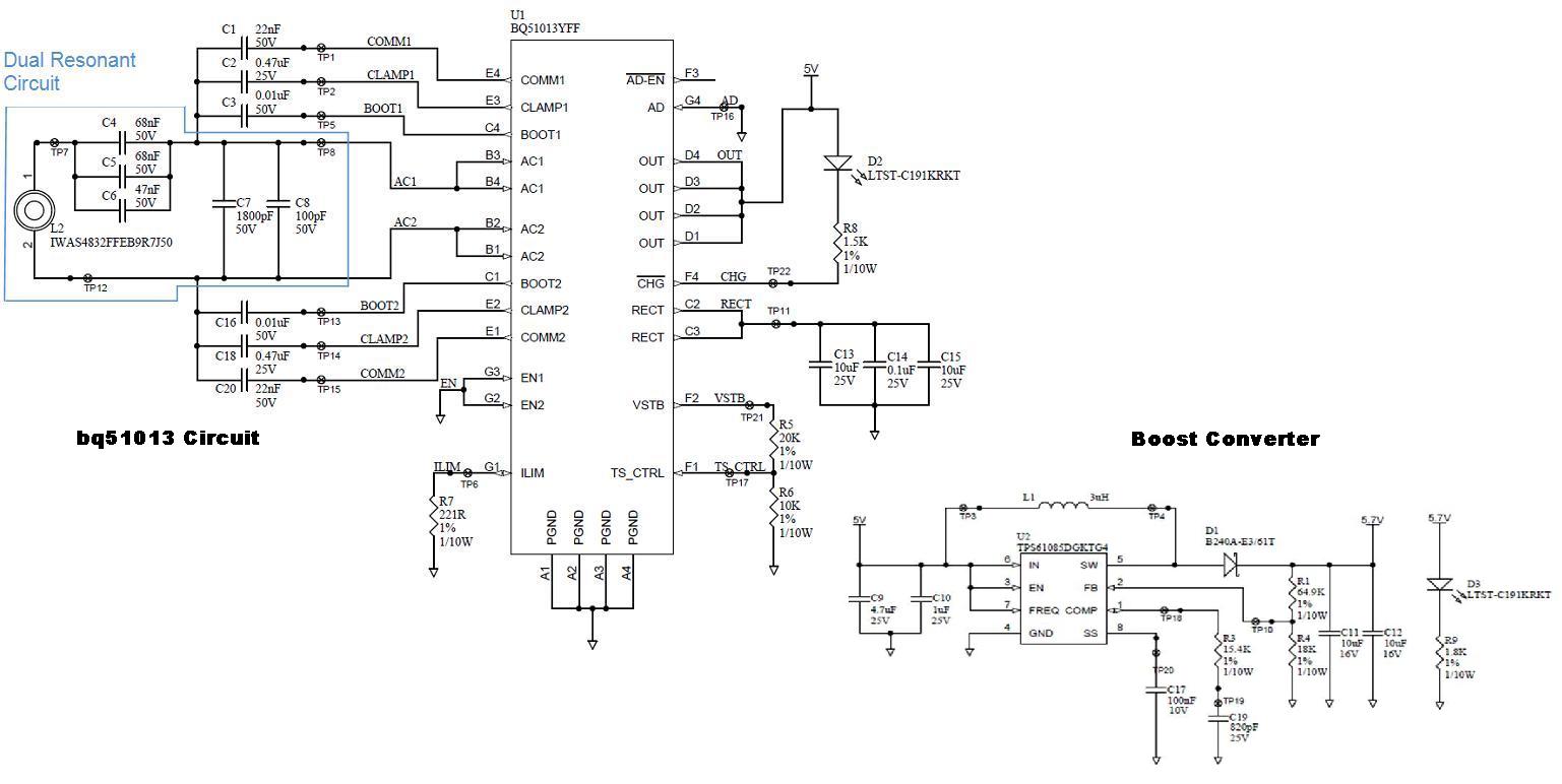
Several boards have been constructed using the bq51013 EVM receiver circuit along with a TPS61085 boost converter circuit, designed in SwitcherPRO Design Software, to elevate the voltage level to 5.7 volts. However, when a load of 580 mA, required...
The circuit illustrated is the receiver component of a transmitter/receiver system designed for tracing electrical wiring paths within a building or identifying breaks in wires. The associated transmitter, which produces a distinctive tone alternating between 2100 Hz and 2200...
Many antique radios operate on batteries, including tube portables like the Zenith model K-401 and "farm" radios used in rural areas without electrical power. This article provides historical context on battery usage in early radios and offers guidance on...
This article discusses simple FM direct conversion radio receivers utilizing a phase-locked loop (PLL). These receivers operate by locking the local oscillator frequency to the input signal. All FM receivers are based on a circuit that combines an oscillator...
The electronic diagram of the monophonic FM receiver made with TDA7088T is shown on Pic.4.12. If built with SMD components it can be placed in a matchbox, altogether with two button-type batteries. The operating principle of this device is...
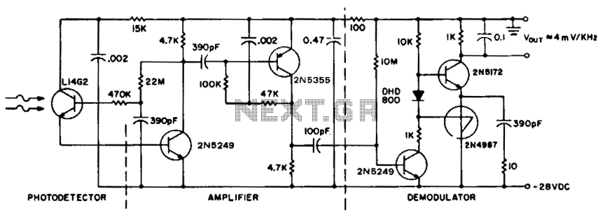
To achieve maximum range, the receiver should be constructed similarly to a radio receiver front end, as the signals received will exhibit comparable frequency components and amplitudes of the photodiode current. The primary limitation on the receiver's performance is...