
FM radio tuning circuit circuit

The FM radio circuit described operates by utilizing a combination of transistors and transformers to achieve effective signal amplification and mixing. The high-frequency amplifier (VT1) plays a crucial role in boosting the weak signals received by the antenna. The input transformer (L1) is essential for impedance matching and ensuring efficient signal transfer to the gate of the amplifier.
The local oscillator (VT2) generates a stable frequency that is mixed with the incoming FM signal in the mixer circuit (VT3). This mixing process produces an intermediate frequency (IF) signal, which simplifies further processing and demodulation. The resonant circuit configured with inductors and capacitors (LC) is pivotal in determining the local oscillator frequency, ensuring that it is properly tuned to the desired signal frequency.
The output from the mixer circuit is then passed through the intermediate frequency transformer (IFT or L4), which is tuned to 10.7 MHz, a common IF frequency for FM radio applications. This stage is critical for filtering and amplifying the mixed signal, allowing for better selectivity and sensitivity of the receiver.
Overall, this FM radio circuit exemplifies the fundamental principles of radio frequency engineering, incorporating various components to achieve robust performance in receiving and processing FM signals. Proper design and tuning of each component are essential for optimal operation and quality of reception in the final audio output.32.FM radio circuit ; FM radio tuning circuit circuit (2) FET circuit in FM radio application tuning circuit is shown in Figure FM radio circuit, which is composed of a high fr equency amplifier VT1, VT3 mixer and local oscillator VT2 and other parts of. FM radio antenna sensing signal, the input transformer Li added, rri gate transistor, VT1 high frequency discharge main amplifier device, after it amplifies the FM frequency signal transformer L2 is applied to the gate of the mixer circuit VT3 pole, yrl2 and LC resonant circuit configuration cost local oscillator, the oscillation signal from the oscillation transformer din secondary source sent to the mixer circuit VT3 pole. Mixer circuit VT3 output from the drain, the intermediate frequency transformer IFT (L4) 10.7 MHz IF output signal.
Related Circuits
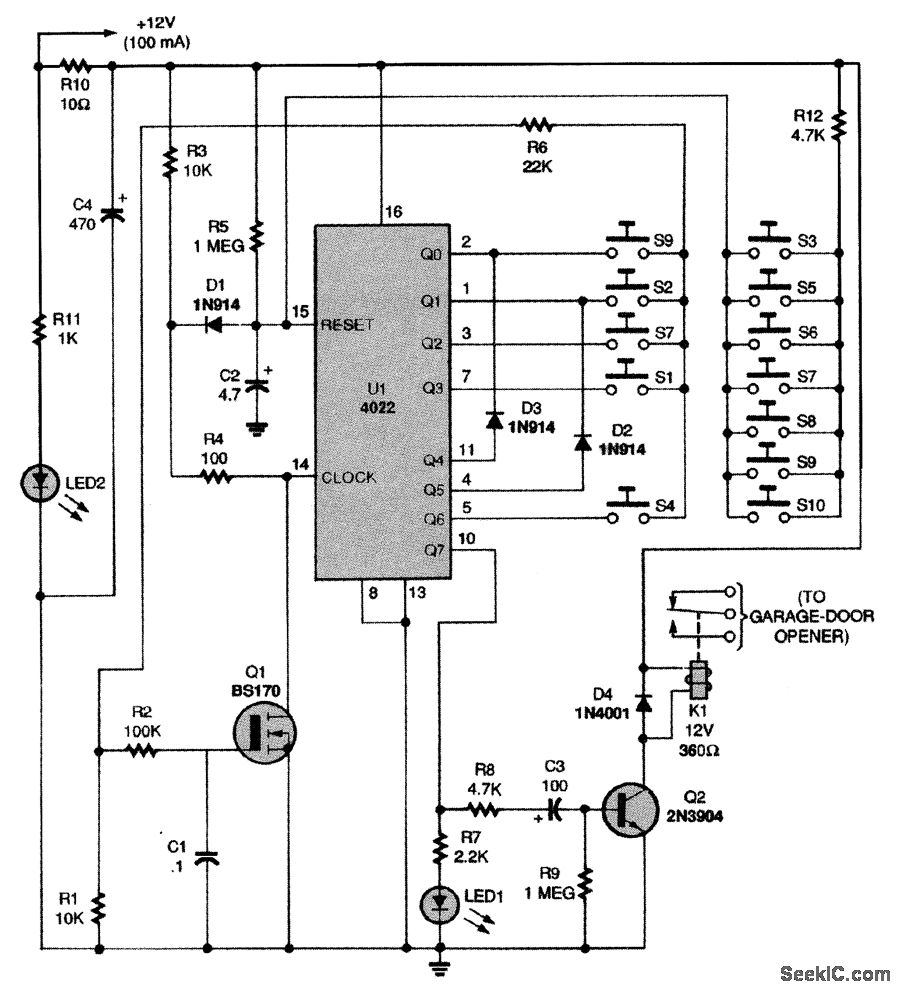
This circuit relies on the input of a correct sequence code. An incorrect number that is not part of the code triggers a reset of the circuit. When the correct code is entered, Q2 activates relay K1 for a...
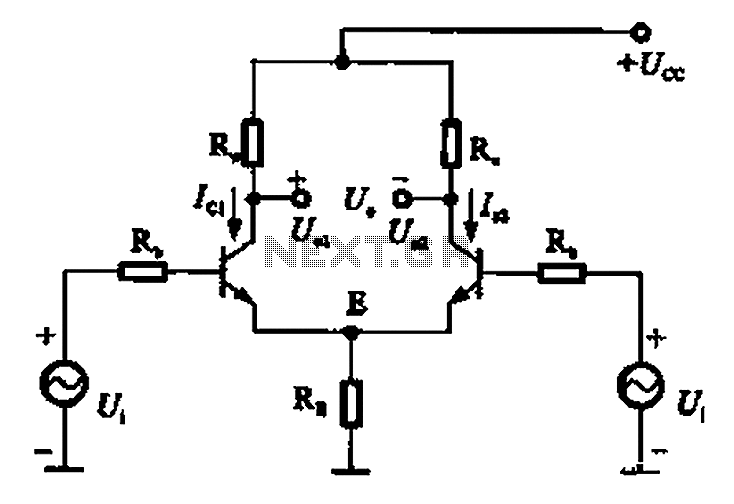
The common mode signal of an emitter-coupled differential amplifier circuit assumes that two equal small increases of the same polarity signal, referred to as the common mode signal, occur simultaneously. This results in an increase in the potential at...
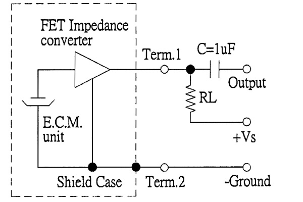
The back of the electret microphone resembles the drawings of the CUI Inc part number CMA-4544PF-W, which will be included in the parts kit. While debugging the data logger software on Windows, an oscilloscope practice lab was conducted using...
This inductance meter serves as an adapter for a digital voltmeter (DVM), enabling the voltmeter to measure the value of inductors. The inductance meter is particularly useful in designing switch mode power supplies, as it often requires hand-winding coils...
The following circuit illustrates the use of the AD8531 integrated circuit for the automatic control of LCD panel backlighting. Features include the ability to compensate for aging effects. The AD8531 is a precision operational amplifier that is well-suited for applications...

This circuit was designed by Lazar Pancic from Yugoslavia. A typical PC sound card includes a microphone input, speaker output, and occasionally line inputs and outputs. The microphone input is specifically tailored for dynamic microphones with an impedance range...