
sound circuit
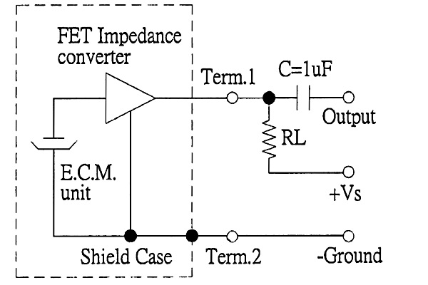
The electret microphone, specifically the CUI Inc CMA-4544PF-W, is a crucial component in audio applications due to its high sensitivity and low power consumption. The microphone operates by converting sound waves into electrical signals through a capacitive effect, where the diaphragm vibrates in response to sound pressure variations. This output signal is typically very weak and requires amplification for processing.
In the described lab setup, the use of a power supply is essential for providing the necessary voltage for the microphone to function optimally. The multimeter, configured as an ammeter, will measure the current flowing through the microphone, allowing students to understand the relationship between current and voltage, which is vital for characterizing the microphone's performance.
The oscilloscope serves as a critical tool for visualizing the electrical signals generated by the microphone. By observing waveforms, students can analyze the frequency response and amplitude of the signals, which will deepen their understanding of audio signal characteristics. The practice of adjusting the oscilloscope settings, such as voltage scaling and time base, is fundamental for accurate measurements and will be an important learning objective.
The experimentation with different voltage levels is designed to illustrate the microphone's operational limits, particularly at low voltages, which can affect its linearity and frequency response. The proposed measurement strategy, utilizing 0.1V increments up to 1V and 1V increments up to 10V, will help students systematically explore the microphone's behavior across its rated voltage range.
The integration of amplifier labs following the microphone experiments will further enhance students' understanding of audio signal processing. The initial operational amplifier configuration aims to demonstrate gain and frequency response, while the subsequent power amplifier lab will introduce concepts of Class AB amplification, providing a comprehensive overview of audio amplification techniques.
Overall, the outlined lab activities are designed to foster hands-on learning experiences, enabling students to engage with fundamental concepts in electronics and audio engineering through practical application and experimentation.The back of the electret mic, which looks just like the drawings of the CUI Inc part number CMA-4544PF-W, the microphone I`ll be including in the parts kit. While my son worked on debugging the data logger software on Windows, I tried out the Oscilloscope practice lab, using the power supply, scope, and multimeter in the lab.
The first bench I s at down (Bench #1) had no power supplies, though I believe that problem will be remedied before classes start (returning the borrowed supplies from another lab or from other benches in the lab, since several had 2 power supplies). The power supplies are quite nice, and provide very precise voltage control, but it will definitely be necessary for the students to use the power supply together with the multimeter set up as an ammeter to measure the DC current through the microphone.
I clearly needed to do more measurements between 0 and 1v, to get a better sense of the shape of the curve there, and the limitations on using the microphone at a low voltage. Had I been by myself, I might have spent more time in the lab, but we had to get my son home for an early dinner so that he could get to his theater practice on time.
I`ll certainly be suggesting to the students in the write up that they use 0. 1 v spacing up to 1 v, then 1v spacing up to 10v (the maximum rated voltage for the mic they`ll be using). It was a good thing I went in before the course started to play with the equipment ”I had expected some trouble with the oscilloscope, since those controls seem to be randomly organized on all digital scopes, but I had not expected trouble with the multimeter.
The fancy ones in the lab have options for front or back connections of the leads, and for triggered or auto-running measurements. It took me a bit of random button pressing to figure out how to turn off the triggering and get continuous measurement.
I also put the microphone in series with a resistor and stuck a scope probe on it. It took me quite a while to get the voltage scaling and time base set reasonably on the digital scope, but I eventually managed to find all the controls I needed, and I think that I can show them to the students. Given the complexity of the user interface for the oscilloscope, I think that the simple measurements of the current vs.
voltage curve and getting the scope to show both continuous waveforms (whistling or speaking) and triggering on a hand clap will be sufficient for the second lab. If students are done sooner, I could have them hook up the frequency meter and try to determine the pitch of their whistling or sustained vowel sounds.
The digital scope does allow seeing much lower frequency waveforms than my analog scope at home, and was clearly able to see 2Hz signals from moving my hand towards and away from the microphone (though 4Hz signals from faster hand movements were much clearer). I still need to decide how many amplifier labs will use the microphone. I was figuring that the first op amp lab would do a gain of around 6 or 7 with AC coupling. And that we`d follow that up with a power amp lab using an nFET and a pFET to make a class AB output stage after an op amp, but I`ve not wired up a power amp circuit yet, and I should do that before I order 20 copies of the transistors.
I think I`ve done all my orders except the Digikey one (and plastic bags to put the parts in). Unfortunately, it looks like WordPress. com lost 2 days worth of edits to the page of parts orders, which is going to be hellishly hard to replace. [Correction: the updates were in the autosave repository, and I was able to restore all but a few minutes work.
Hooray for autosave!] 🔗 External reference
Related Circuits
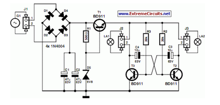
A front wheel with a built-in dynamo was purchased, providing a sine wave output of 30 Vpp at no load. Based on this, a simple power supply was designed using BD911 transistors, which are somewhat oversized for the application,...
This circuit functions as a night lamp when a wall mains socket is unavailable for plugging in a continuously operating small neon lamp device. To minimize battery consumption, it utilizes a single 1.5V cell, and a simple voltage doubler...
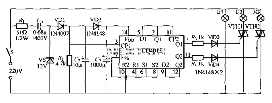
Figure 296 illustrates a control circuit that utilizes a switch (S) to manage three lamps (E1, E2, and E3) in a lighting system, suitable for controlling a chandelier in a living room. When the switch is off, all lights...
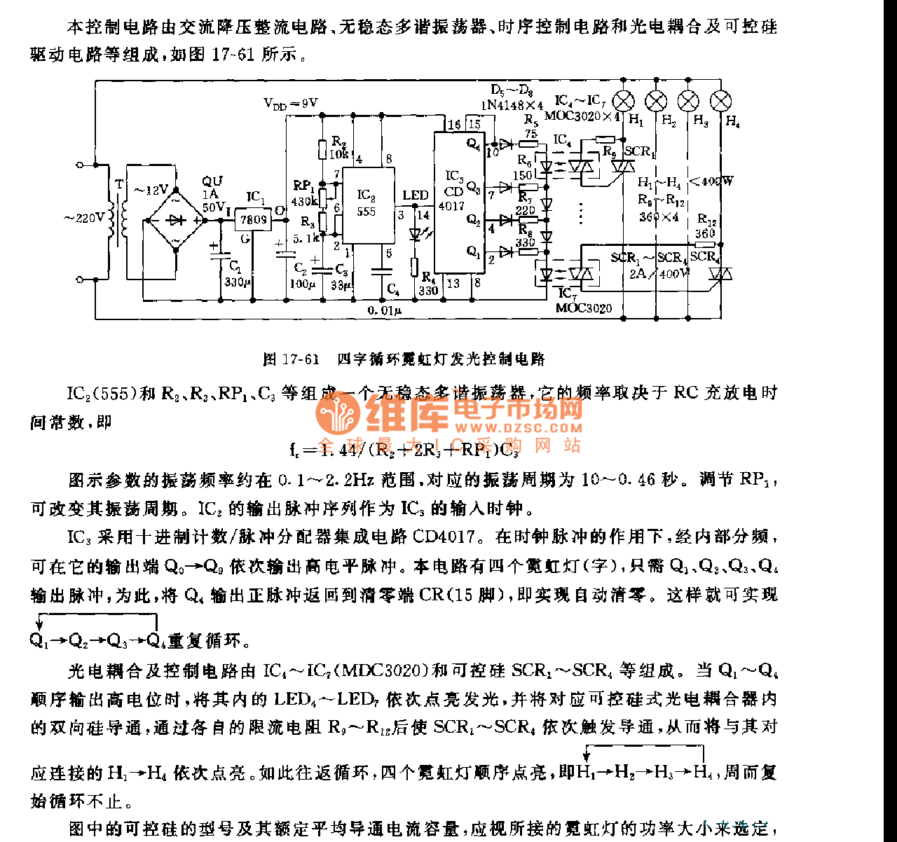
This control circuit consists of an AC step-down rectifier circuit, an astable multivibrator, a timing control circuit, an optocoupler circuit, and an SCR driving circuit, as illustrated in Figure 17-61. The astable multivibrator is formed using IC2 (555), resistors...

This circuit is designed as a countdown timer utilizing a countdown calculation. It employs the 555 integrated circuit (IC) as the primary control element. The 555 IC functions as a counter and a transistor switch to activate a relay...
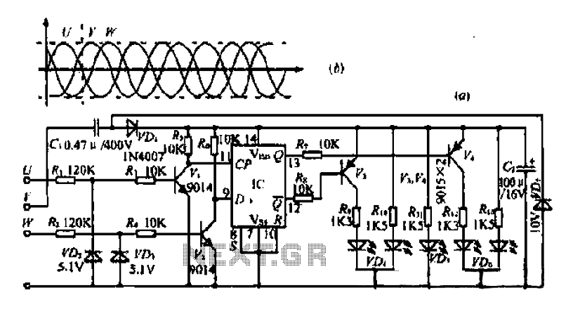
The three-phase voltage waveform diagram illustrates that when one phase voltage transitions from positive to negative across the zero point, the subsequent phase voltage becomes positive while the third phase remains negative. The U terminal voltage is positive when...