
Frequency counter Input schematic
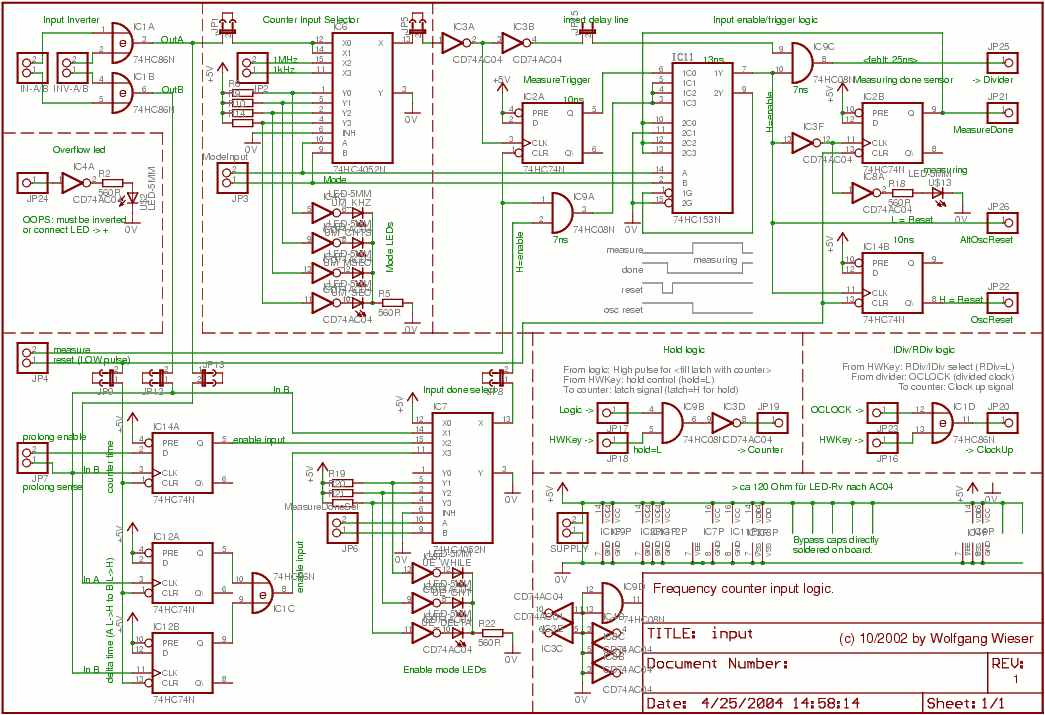
The circuit utilizes a master mode selection switch (IC6) that effectively manages the operation of the frequency counter and time measurement system. The four mode LEDs indicate the current measurement unit, which corresponds to different operational modes. The switch's output is routed through IC9C, an AND gate that controls the connection to the divider and counter based on the selected mode. The architecture ensures that the measurement process is tightly controlled through the use of IC11, which provides the necessary enable signals to the measurement logic.
The integration of flip-flops (IC2A, IC12A, IC12B, and IC14) allows for precise timing and control over measurement initiation and termination. The feedback mechanism prevents erroneous re-triggering of measurements, ensuring reliability in the system's performance. The use of dedicated clock sources (1 MHz and 1 kHz) ensures accurate timing for both frequency counting and time measurement, while the microcontroller's role in processing the measurement results is critical for the overall functionality of the device.
The enable logic section, comprising IC7 and additional flip-flops, provides a flexible interface for controlling measurement modes, allowing for dynamic adjustments based on the input signals. This feature is particularly useful for applications requiring precise timing and counting capabilities. Overall, the circuit design reflects a thoughtful approach to managing complex measurement tasks, ensuring accuracy and reliability across various operational modes.The master mode selection switch is IC6 which switches the 4 mode LEDs (which also correspond to the measured unity, i. e. kHz, counts, milli-seconds or seconds) as well as the input for the divider and the counter : For standard frequency counter mode (mode: 0, unity: kHz) as well as counter mode (mode: 1, unity: counts), the input A is used (for
divider, etc); for both time measurement modes (mode: 2, 3; unity msec, seconds), the fixed 1MHz and 1kHz clock sources are used. This, of course, requires that there is another switch which acts as a gate to control exactly how long the output of the master mode switch is conntected to the divider and counter : This is IC9C, an AND gate whose enable input (pin10) is controlled by IC11: In counter and time measurement modes, this enable input is simply the AND (IC9A) of the measure signal from the logic board and the enable signal from the enable logic (left bottom in the sheet).
For frequency counter mode, this enable logic has no use but here, the IC2A edge-triggered (D-type) flip-flop makes sure that the measurement actually starts at a HIGH-to-LOW transition of the input signal (this is the reason for the 2 inverters IC3A, B. When the measure signal from the logic board is LOW, the flip flop IC2A is reset (pin1) and hence provides similar functionality as the IC9A AND gate for the other modes.
frequency counter mode, the In order to detect when measurement is finished, the "measuring done sensor" IC2B is used which triggers on the HIGH-to-LOW transition of the enable signal (IC11`s pin7). Especially note the "feedback loop" from pin9 to pin1 of IC11 which makes sure that once the measurement is finished (i.
e. IC2B`s pin9 feeds HIGH into IC11`s pins 10, 12, 13), it is not re-started again before there was a reset pulse on the reset line delivered by the logic board. (For obvious reason, no such feedback is provided for counter mode. ) For time measurement mode and frequency counter mode, IC14B plays an important role: It makes sure that the 1kHz oscillator starts running just at the time when the enable signal (IC11`s pin7) goes HIGH so that the n-th 1kHz clock tick is finished exactly n msec after the start of the measurement.
(This holds also for frequency counter mode where the microcontroller on the logic board counts 100 to 10000 ticks of the 1kHz clock (i. e. gate times of 0. 1 to 10 seconds) to decide when to end the measurement. ) Otherwise an error of 0 to 1 msec would be introduced. Note also that no such synchronisation is provided for the 1MHz clock of the other (msec) time measurement mode which means that it always has an error of max.
1usec. (This clock is also needed to clock the microcontroller on the logic board. ) In order to end a running measurement, either the logic board sets the enable signal to LOW (which is the only method for frequency counter mode: the microcontroller here uses the 1kHz clock for the gate timing) or when the enable logic (on the left bottom of the sheet) decides to do so. In any case, the microcontroller is informed about the end of the measurement via the measuing done signal on JP21.
The enable logic on the left bottom of the sheet is formed of the enable mode selector IC7 (with corresponding LEDs) and the 3 edge-triggered D-type flip-flops IC14, IC12A and IC12B. Enable mode 0 (standard) means "enable always" (IC7`s pin12) while mode1 means "enable as long as input B is HIGH".
The modes 2 and 3 are more complex: Mode2 uses IC14 to make the enable signal change upon a LOW-to-HIGH transition of the inputB. Note that the logic board has rough control over it since it provides the D input of the flip-flop. This allows to e. g. measure the time of 1, 10 or 100 pulses of some signal on inputB by using the logic to count 0, 9 or 99 pulses and then set prolong (the D input) to LOW so that the next rising edge of inputB will actually stop the measurement.
Mode3 finally allows to 🔗 External reference
Related Circuits
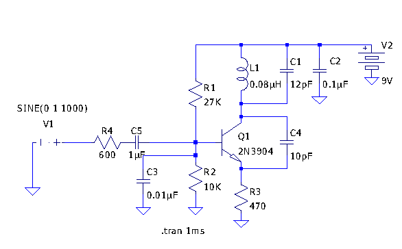
Here is a little audio amplifier similar to what you might find in a small transistor radio. The input stage is biased so that the supply voltage is divided equally across the two complimentary output transistors which are slightly...
Another application of the frequency-to-voltage converter (FVC) is as a tone or frequency decoder. This circuit is utilized to identify the frequency band of an oscillation. The frequency-to-voltage converter (FVC) serves as an essential component in various electronic applications, particularly...
Tetsuo Kogawa's circuit is well documented, although not in a conventional schematic form. It has been entered into LTSpice for analysis, and the schematic is presented online with some comments. The circuit includes a small air variable capacitor (C1)...
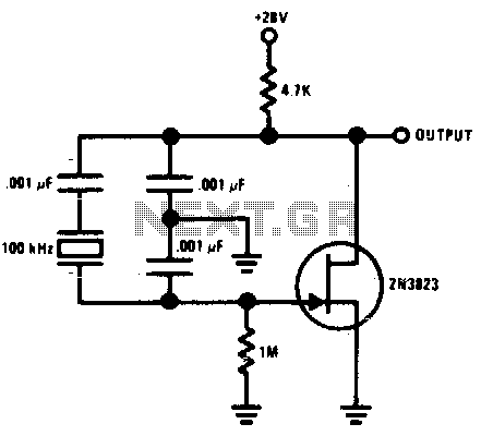
This Colpitts crystal oscillator is ideal for low-frequency crystal oscillator circuits. Excellent stability is assured because the 2N3823 JFET circuit loading does not vary with temperature. The Colpitts crystal oscillator is a type of electronic oscillator that utilizes a combination...
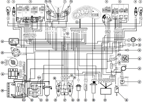
The following presents an electrical schematic for a 1993 VW Passat. Features include vehicle content and electrical wiring schematic. Components consist of console switches, electric windows, ABS control unit, ABS hydraulic unit, engine control module, automatic control unit, fuse/relay...

Frequency converter schematic, frequency to voltage converter schematic, frequency to voltage converter using TR, voltage to frequency converter application. A frequency converter is an essential electronic circuit that transforms frequency signals into corresponding voltage levels or vice versa. The frequency...