
Frequency converter circuit

A frequency converter is an essential electronic circuit that transforms frequency signals into corresponding voltage levels or vice versa. The frequency to voltage converter schematic is designed to provide a linear output voltage that is proportional to the input frequency. This is particularly useful in applications where frequency signals need to be monitored or processed, such as in signal processing or control systems.
The frequency to voltage converter using a transistor (TR) typically employs a configuration where the input frequency signal is fed into a transistor circuit. The transistor operates in a switching mode, converting the frequency variations into a varying voltage output. The output voltage can then be further processed or displayed, providing a clear representation of the input frequency.
On the other hand, the voltage to frequency converter application is designed to achieve the opposite function, where an input voltage signal is converted into a frequency output. This type of converter is useful in telemetry systems and for generating frequency-modulated signals. The circuit generally utilizes operational amplifiers and other components to ensure that the output frequency is accurately proportional to the input voltage.
Both types of converters can be integrated into various electronic systems, enabling effective communication, control, and monitoring of frequency-based signals. Proper design considerations include component selection, circuit stability, and the linearity of the conversion process, which are crucial for achieving desired performance in practical applications.Frequency converter schematic, frequency to voltage converter schematic, Frequency to Voltage Converter Using TR, Voltage to Frequency Converter Application 🔗 External reference
Related Circuits
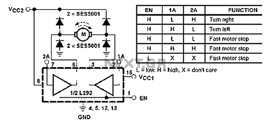
All inputs are compatible with TTL. Each output consists of a complete totem pole driver circuit, utilizing Darlington transistors and pseudo-Darlington sources. The driver enable signals, labeled as 1,2 EN and 3,4 EN, control the activation of drivers 1...
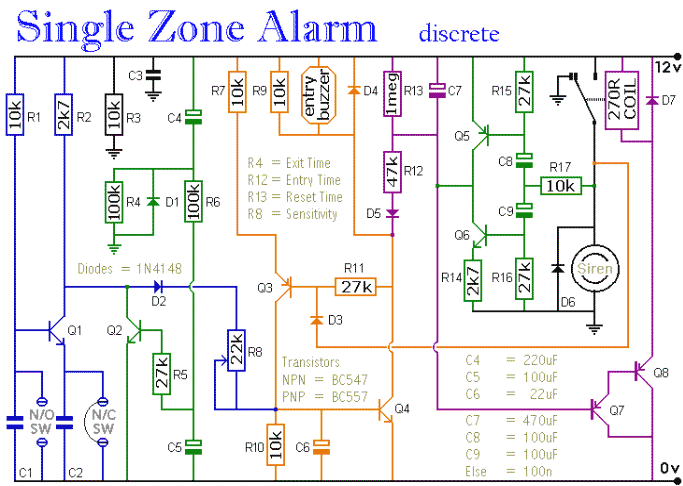
The circuit includes automatic entry and exit delays, a timed bell cut-off, and a system reset feature. It accommodates both normally open and normally closed switches, making it compatible with common input devices such as pressure mats, magnetic reed...
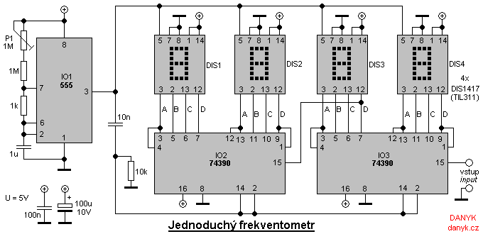
A simple digital frequency meter has various applications, serving as an experiment for beginners, laboratory equipment, or a meter integrated into certain devices. It is ideal for situations where frequency measurement and digital display are required. The frequency meter...
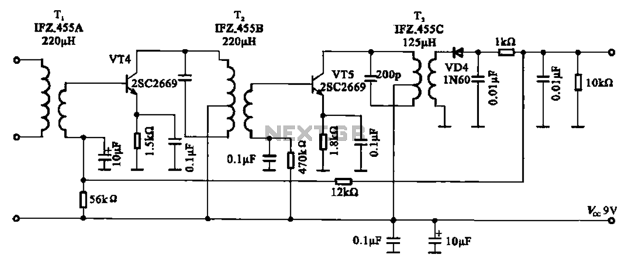
AM radio shows the IF amplifier and detector circuit. The mixer receives the intermediate frequency output signal from the transformer after the device. This signal is applied to the base of the intermediate frequency transistor VT4. The collector load...
A larger version of the circuit diagram can be accessed by clicking here. The circuit was created using Eagle from CadSoft, which is a free schematic and PCB layout software for small non-commercial projects. The core component of the...
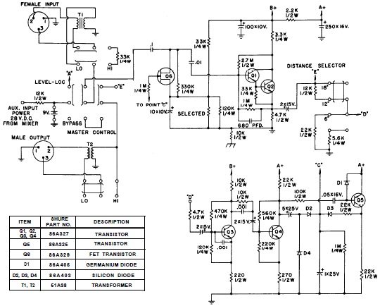
SHURE is an American corporation that manufactures consumer and professional audio electronics, including microphones, phonograph cartridges, and discussion systems. SHURE Incorporated is a well-established entity in the audio electronics industry, recognized for its innovative design and high-quality products. The company...