
Frequency counter Oscillator schematic
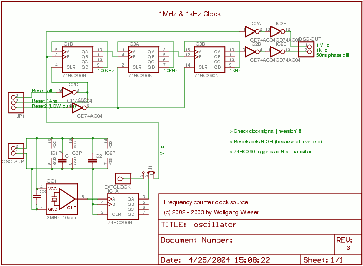
The oscillator circuit is designed to produce two distinct clock frequencies: 1 MHz and 1 kHz. The 1 MHz clock signal is critical for the operation of the microcontroller, providing the necessary timing for processing instructions and executing tasks. Additionally, this clock serves as a time base for millisecond measurements, which are essential for time-sensitive applications.
To achieve the required 50% duty cycle, a 2 MHz clock signal is generated and then divided by 2. This division can be accomplished using a flip-flop or a frequency divider circuit, ensuring that the output maintains the desired duty cycle for reliable operation.
The design incorporates three half HC390 binary counters configured to divide the frequency by 1000. This division is essential for generating the 1 kHz clock signal from the 1 MHz source. The capability to externally reset these counters allows for greater flexibility in timing applications, ensuring that the millisecond timer can start precisely when needed, which is crucial for accurate timing and event measurement.
In addition to the frequency division, AC04 integrated circuits are used as drivers and buffers. These components are instrumental in ensuring signal integrity and providing sufficient drive capability for the connected loads. The use of buffers helps to isolate the oscillator from the rest of the circuit, preventing loading effects that could alter the frequency or duty cycle.
The inclusion of connector J1 provides the option to utilize an external clock source, allowing for adaptability in various applications. This feature can be particularly useful in scenarios where synchronization with other systems is required or when a specific clock frequency is needed beyond the internal capabilities of the oscillator circuit.
Overall, this oscillator circuit is a versatile solution for generating precise clock signals and ensuring accurate timing in microcontroller-based systems.The oscillator provides a 1MHz and a 1khz clock. The 1MHz clock is used as the clock for the microcontroller and as timebase for millisecond measurement. I use a 2MHz and divide it by 2 in order to guarantee a 50% duty cycle. Then three halve HC390 are used as divider by 1000 which can be externally reset. This is necessary to make sure the millis econd timer starts running at the time it is needed. AC04 are used as drivers/buffers. J1 allows the use of an external clock. 🔗 External reference
Related Circuits
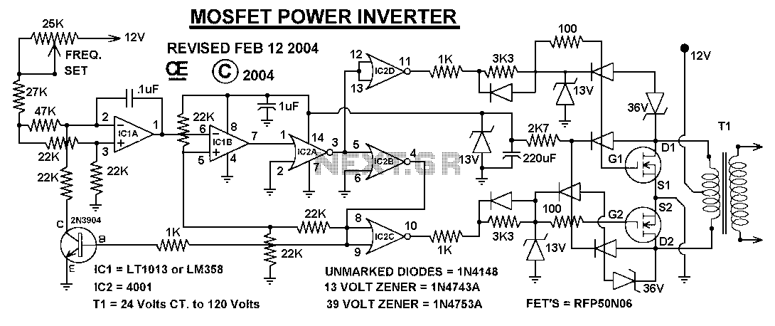
This power inverter circuit provides a stable square wave output voltage. The frequency of operation is set by a potentiometer and is typically adjusted to 60 Hz. Various off-the-shelf transformers can be utilized, or custom-wound transformers can be created...
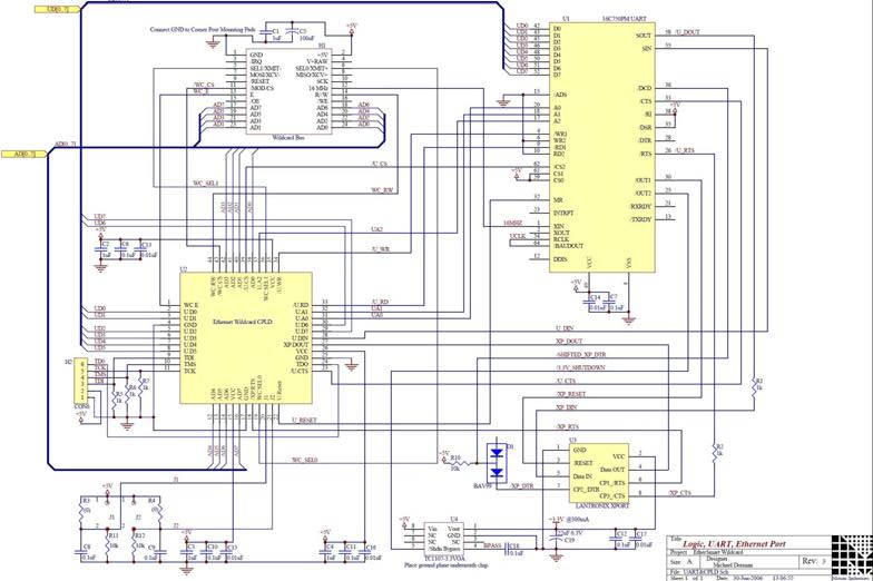
The EtherSmart Wildcard is based on the Lantronix Xport Ethernet device server, which is integrated into an RJ-45 connector housing. The Xport communicates data through a serial UART-USART interface, while the Wildcard bus operates as a parallel interface. A...
This chapter contains circuit diagrams for several power supplies for pulsed solid-state lasers. These include units suitable for driving the popular Hughes ruby and YAG rangefinder laser assemblies, one utilizing the flash from a disposable pocket camera, and a...
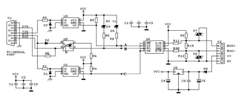
RS232 to RS485 Converter Circuit Schematic. RS232 to RS485 converters are primarily utilized in industrial and commercial settings. The RS232 to RS485 converter circuit is designed to facilitate communication between devices using different serial communication standards. RS232 is commonly found...
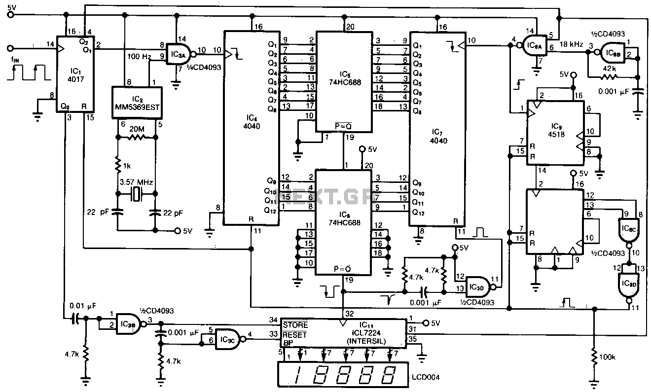
This tachometer allows for the measurement of heartbeats, respiratory rates, and other low-frequency events that occur at intervals ranging from 0.33 to 40.96 seconds. The circuit detects the frequency, calculates the corresponding pulses per minute, and updates the LCD...
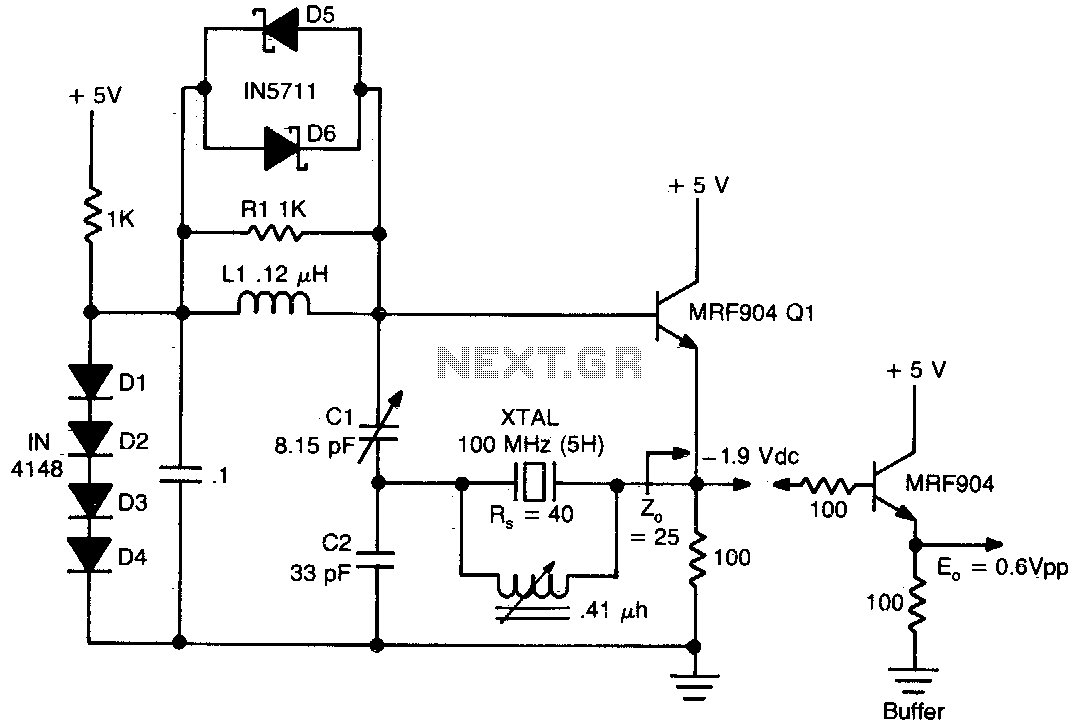
This circuit exhibits good performance without an amplifier, having a gain of only one, with built-in parasitics due to the emitter follower negative feedback. Additionally, it serves to stabilize its gain. The circuit under discussion utilizes an emitter follower configuration,...