
Ethernet Hardware Schematics
The EtherSmart Wildcard provides a robust solution for integrating Ethernet connectivity into various devices, utilizing the Lantronix Xport as its core component. The Xport device server is housed within an RJ-45 connector, facilitating easy integration into existing network infrastructures. The communication between the Xport and the connected devices is achieved through a serial UART-USART interface, which is essential for transmitting data in a serial format, while the Wildcard bus operates in parallel, allowing for multiple data lines to be managed simultaneously.
The UART chip on the EtherSmart board plays a critical role in bridging the communication gap between the parallel Wildcard bus and the serial data lines of the Xport. This conversion is vital for ensuring that data can be effectively transmitted and received in the appropriate formats required by both the Wildcard bus and the Xport.
Furthermore, the built-in software capabilities of the EtherSmart Wildcard enhance its functionality significantly. The ability to send emails directly from the instrument allows for real-time notifications and alerts, which can be crucial in monitoring and automation applications. The serving of static and dynamic web pages enables users to interact with the device through a standard web browser, providing a user-friendly interface for configuration and data visualization.
The Serial Tunneling feature allows for a seamless exchange of serial data with peripheral devices, expanding the EtherSmart Wildcard's versatility in various applications. This capability is particularly beneficial in scenarios where remote monitoring and control of devices are necessary.
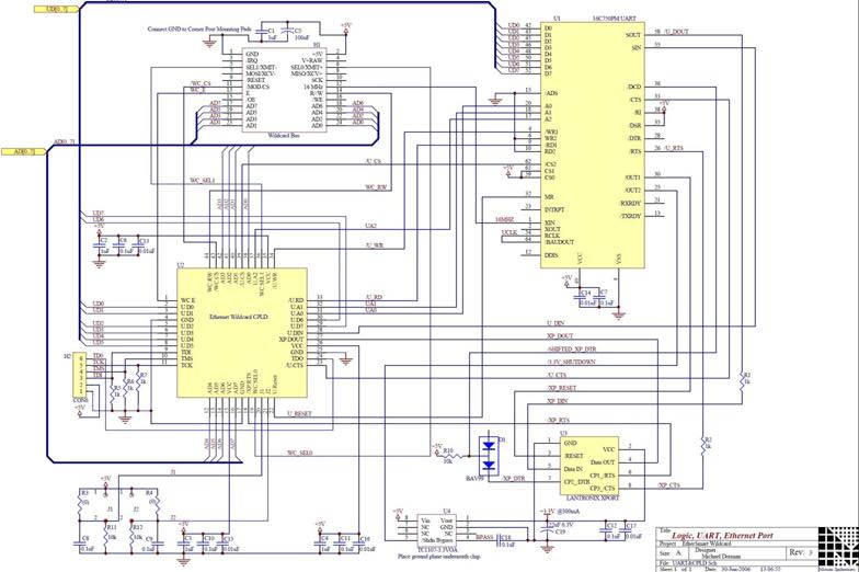
Overall, the EtherSmart Wildcard is designed to facilitate web-enabled instrumentation and automation applications, making it an invaluable component in modern electronic systems that require reliable Ethernet connectivity and data communication capabilities. The associated hardware schematics provide detailed insights into the design and implementation of the EtherSmart Wildcard, showcasing its integration with the Lantronix Xport Ethernet device server.The EtherSmart Wildcard is based on the Lantronix Xport Ethernet device server which is built into an RJ-45 connector housing. The XPort exchanges data via a serial UART -USART interface, while the Wildcard bus is a parallel interface.
A UART (Universal Asynchronous Receiver/Transmitter) chip on the EtherSmart board implements the conversion between the parallel Wildcard bus and the XPort`s serial data lines. Built-in software lets you send emails from the instrument, serve out static and dynamic web pages to your PC-based browser, and implement serial data exchanges with peripheral devices (known as Serial Tunneling). The EtherSmart Wildcard is ideal for web-enabled instrumentation and automation applications. This page is about: Ethernet Hardware Schematics, Lantronix Xport EtherSmart Wildcard hardware schematics, based on the Lantronix Xport Ethernet device server.
🔗 External reference
Related Circuits

This circuit is designed for a 40 Watt fluorescent lamp. It operates similarly to a traditional strobe light, but utilizes a fluorescent tube instead. The fluorescent tube remains continuously energized, with both electrodes supplied with electricity. This current causes...

This digital thermometer circuit diagram utilizes a common 1N4148 diode as the temperature sensor. The diode's temperature coefficient of -2 mV/°C is leveraged to create an accurate electronic thermometer. A digital multimeter is employed to display the measured temperature,...
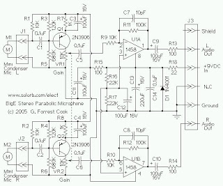
The mini condenser microphone converts sounds into an electrical signal. Resistor R1 provides bias for the condenser microphone's internal amplifier transistor. The 2N3906 PNP transistor acts as a low-noise microphone input amplifier. The 10K gain potentiometer is used for...
This chapter contains circuit diagrams for several power supplies designed for pulsed solid-state lasers. These include units suitable for driving the widely used Hughes ruby and YAG rangefinder laser assemblies, one utilizing the flash from a disposable pocket camera,...
A graphical representation of a system. It often refers to electronic circuits on a printed circuit board or in an integrated circuit (chip). See logic gate and HDL. A graphical representation of a system serves as a crucial tool in...
A mute switch for the Etherwave that adds a "mute status" light, which also functions as a power-on indicator. The schematic is provided. It is recommended to explore the additional resources available on Art's website. The mute switch circuit for...