
Frequency-doubler
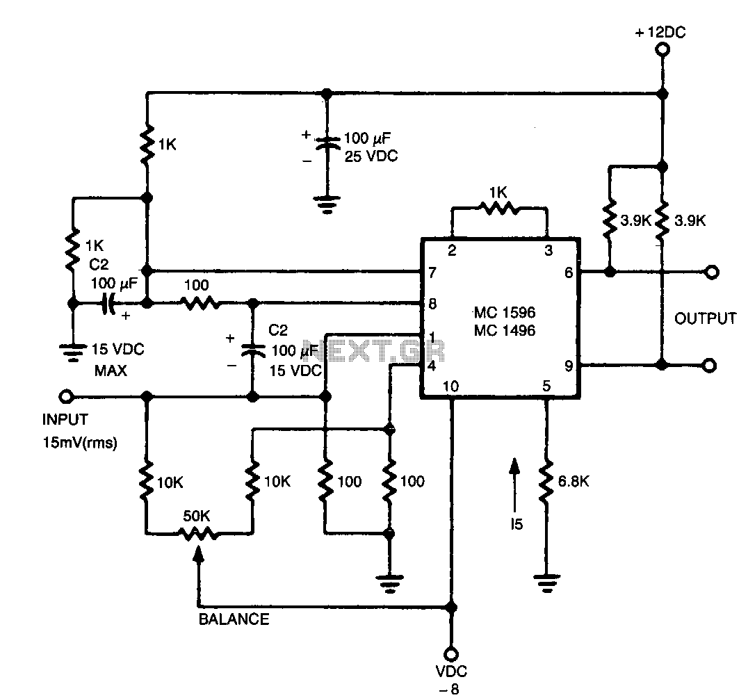
The output contains the sum component, which is twice the frequency of the input, since both input signals are of the same frequency.
In a circuit design context, the described output suggests the presence of a frequency doubling mechanism, commonly implemented using a nonlinear device such as a diode or a dedicated frequency doubler IC. In this configuration, two input signals, which are identical in frequency, are fed into the circuit. The nonlinear characteristics of the device generate harmonics of the input frequency.
The fundamental principle is that when two identical signals are combined, the interaction can produce a new signal at twice the frequency of the original inputs. This is often achieved through mixing or modulation techniques. For instance, if the input frequency is represented as \( f \), the output frequency can be expressed as \( 2f \).
In practical applications, such as in RF (radio frequency) communication systems, frequency doublers are crucial for generating higher frequency signals from lower frequency sources, facilitating efficient transmission and reception of signals over long distances. The design may include filters to eliminate unwanted harmonics and noise, ensuring that the output signal is clean and usable for further processing or amplification.
The schematic for such a circuit would typically include two input terminals for the signals, a nonlinear element (such as a diode), and output terminals where the doubled frequency signal can be accessed. Additional components like resistors, capacitors, and inductors may be incorporated to optimize performance, stabilize the output, and manage impedance matching.The output contains the sum component, which is twice the frequency of the input, since both input signals are the same frequency. 🔗 External reference
Related Circuits
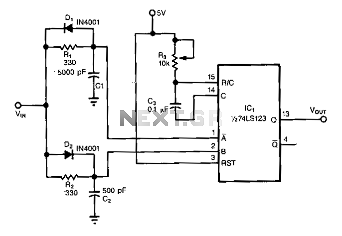
The frequency doubler utilizes a single integrated circuit (IC). Similar to other frequency doublers, this circuit leverages both the rising and falling edges of the input signals to generate digital pulses, effectively doubling the input frequency. In the absence...
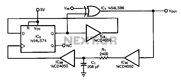
The circuit doubles the frequency of a digital signal by operating on both signal edges. Each transition causes the exclusive-OR gate IC1 to produce a pulse, which clocks flip-flop IC3 after propagating through buffers IC2C and IC2B. If capacitor...
Warning: include(partials/cookie-banner.php): Failed to open stream: Permission denied in /var/www/html/nextgr/view-circuit.php on line 713
Warning: include(): Failed opening 'partials/cookie-banner.php' for inclusion (include_path='.:/usr/share/php') in /var/www/html/nextgr/view-circuit.php on line 713