
Geiger Counter

The circuit design described is a high-voltage charging circuit that is engineered to produce voltages exceeding 500V, with the output voltage primarily influenced by the inductor specifications and component characteristics. The inclusion of a 10 MΩ resistor is a critical safety feature, ensuring that the current output remains below 60 µA, which mitigates the risks associated with short circuits. The flexibility in transistor selection allows for the use of widely available components, ensuring the circuit can be easily assembled using alternative transistors with similar ratings.
The diodes employed in this circuit must have a voltage rating of at least 600V to ensure reliable operation under high-voltage conditions. The specified choke, a 15 mH inductor with a ferrite core, helps regulate the current flow and can be substituted with inductors of similar values if necessary. The capacitors, while rated for lower voltages, should be adequately chosen to handle the circuit's operational demands, particularly in high-voltage applications.
The voltage regulation mechanism utilizing NE-2 lamps provides a unique aesthetic while serving the functional purpose of voltage regulation. This approach may be preferable to zener diodes, particularly in applications where power consumption is not a primary concern. The audio amplification stage, based on the LM386N chip, is designed to process signals from the Geiger-Muller tube effectively, ensuring that the detection events are audible.
To enhance the overall performance and reliability of the circuit, it is recommended to house the entire assembly in a grounded metal enclosure. This not only provides physical protection but also minimizes electromagnetic interference, which could affect the operation of the Geiger-Muller tube and the audio output. The use of a shielded coaxial cable for the connection to the Geiger-Muller tube further improves signal integrity by reducing noise and interference from external sources.
In summary, this high-voltage charging circuit combines safety, functionality, and aesthetic appeal, making it a versatile project for enthusiasts interested in radiation detection and audio amplification applications. The careful selection of components and design considerations ensures reliable performance while allowing for customization and adaptability.The basic charging circuit produces in excess of 500V+, depending on the inductor used, leakage of various components, etcetera. The current output is limited by a 10Mohm resistor, which keeps short-circuit current under ~60uA. Thus this is a relatively safe project. The transistors used are by no means sacred; this design can be seen in several places across the web, and no two schematics use similar
transistors. The 2N3904 could be replaced with a 2N2222, the 2N3906 with a 2N2907, and so on. The 2N6517 is rated at 350V collector-emitter, so a substitute NPN transistor should meet these specifications. If in doubt, download some datasheets and see what looks like it will work. All four diodes should be rated for at least 600V. 1N4007`s are common, but anything similar can be used. The 15mH choke is a small, 0. 75" x. 2" diameter epoxy encapsulated inductor with a ferrite core. Anything around this value should work. If all you`ve got is a few 4. 7mH, just put two or three in series. The 0. 01uF capacitors should be rated for 300V or so. Given the low currents involved, this may not be absolutely necessary. For the `voltage regulator`, two NE-2 lamps are used; I`ve seen versions of this which used harder to acquire zener diodes.
In my experience, all zeners do is cut down on power consumed by the supply, which here at United Neko is the least of concerns. You are most likely not going to be using this in a post-Apocalyptic world where batteries are scarce.
The neons also look a bit more impressive as they gently flicker in their distinctive orange hue. The audio stage is simply an LM386N audio amplifier chip, probably one of the most common out there. If you don`t like this chip (many people do not, and it does give me hell at times), you could use an amp made from discrete transistors. Doesn`t really matter, as long as it can pick up the click from the counter tube. The 68pF capacitor cuts down on noise (particularly 60 cycle hum) entering the audio stage, while easily passing the high-risetime impulse of a detection `count.
` It should be rated for at least 600V, more if available, as it also keeps HVDC from the charging supply/G-M tube anodefrom reaching the amplifier input, while passing AC signals. Additional shielding which is recommended is to build the entire circuit (battery as well) inside of a metal box, preferably steel, and have the metal enclosure common with circuit ground.
An RCA jack mounted on the side of this enclosure allows a shielded coaxial cable of about 3 foot length to connect with the G-M tube itself. This has the advantage of further shielding the counter signal from outside spurious influence, allows the tube to be enclosed in a wand for easy manipulation by hand, and adds a measure of isolation of the anode supply wire.
The speaker was obtained from a scrapped handheld FM radio, and is about 1 1/2" diameter. The hardest part to obtain is also the key to the whole thing: the Geiger-Muller tube itself. There are a few different variants available; some are entirely composed of glass. These will work well for detecting gamma and X-rays, but will not allow you to detect alphas or much beta. They are cheap, however, and readily available on p 🔗 External reference
Related Circuits
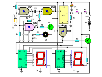
This is a simple digital pulse counter featuring 7-segment LED displays. The design allows for any number of digits, utilizing decimal counters such as the 4026 (including variants like MH4026, HCF4026, CD4026, etc.). An advantage of this configuration is...
This circuit measures the distance covered during a walk. The hardware is housed in a small box that can be placed in a pocket, and the display is designed as follows: the leftmost display D2 (the most significant digit)...
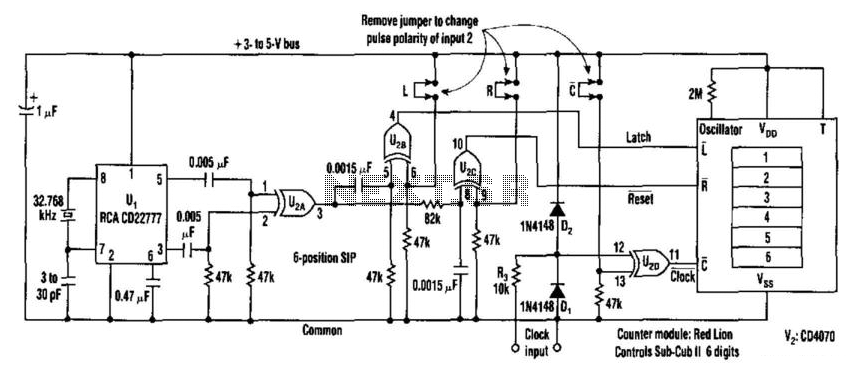
This counter facilitates the direct readout of frequency-generating equipment by incorporating a 1-Hz time base to latch, reset, and condition the count signal. The design allows for the selection of either polarity. By differentiating, inverting, and ORing the clock...
This room light controller project automatically uses a microcontroller to manage a visitor counter, providing a reliable circuit for controlling the room lighting. The room light controller circuit integrates a microcontroller that processes inputs from a visitor counter. This setup...
This circuit measures the distance covered during a walk. The hardware is housed in a small box that can be slipped into a pocket, and the display is designed as follows: the leftmost display D2 (the most significant digit)...
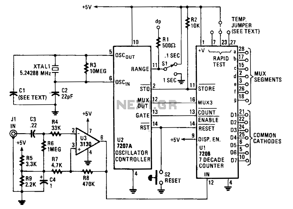
The circuit comprises an ICM7208 seven-decade counter (U1), an ICM7207A oscillator controller (U2), and a CA3130 biFET operational amplifier (U3). The ICM7208 (U1) counts input signals, decodes them into a 7-segment format, and outputs signals to drive a 7-digit...