
Digital Step-Km Counter Circuit Schematic
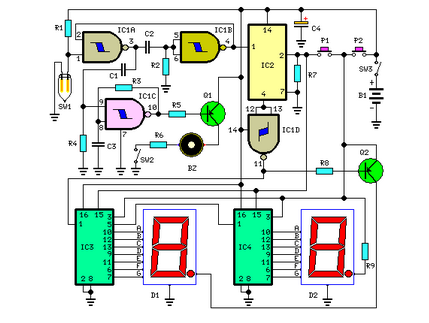
The circuit operates on the principle of measuring steps taken by the user, translating physical movement into distance measurements. The integration of a mercury switch is crucial, as it detects the tilt caused by movement, generating a pulse for each step taken. The monostable multivibrator configuration (IC 1A and IC 1B) serves to filter out noise and ensure that only clean pulses are counted, which is essential for maintaining the accuracy of the distance measurement.
The division of the pulse signal by 64 using IC2 allows for a manageable output that can be further processed to drive the displays. The dual display system, utilizing D1 and D2, provides a clear and user-friendly interface for reading distances. The dot indicators serve as visual cues, enhancing user experience by clearly delineating kilometers from hectometers and indicating the completion of every 50-meter segment.
The design includes user-friendly features such as the ability to reset the counters and enable/disable the display and beeping function. This flexibility allows for customization based on user preference and battery conservation needs. The careful placement and adjustment of the mercury switch are paramount, as improper positioning could lead to inaccurate readings, particularly during more dynamic activities like jogging.
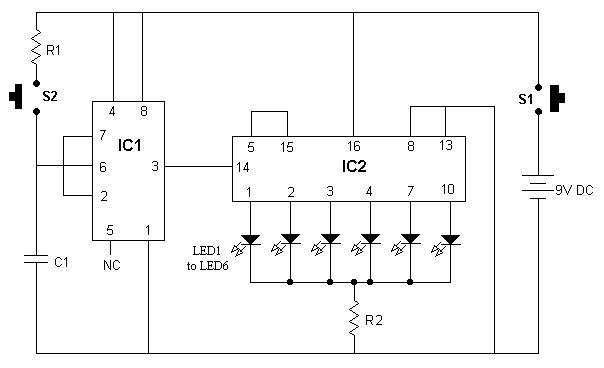
Overall, this circuit exemplifies a practical approach to distance measurement for walkers, balancing simplicity, functionality, and user interactivity in a compact design.This circuit measures the distance covered during a walk. Hardware is located in a small box slipped in pants` pocket and the display is conceived in the following manner: the leftmost display D2 (the most significant digit) shows 0 to 9 Km. and its dot is always on to separate Km. from hm. The rightmost display D1 (the least significant digit) sh ows hundreds meters and its dot illuminates after every 50 meters of walking. A beeper (excludable), signals each count unit, occurring every two steps. A normal step was calculated to span around 78 centimeters, thus the LED signaling 50 meters illuminates after 64 steps (or 32 operations of the mercury switch), the display indicates 100 meters after 128 steps and so on. For low battery consumption the display illuminates only on request, pushing on P2. Accidental reset of the counters is avoided because to reset the circuit both pushbuttons must be operated together.
Obviously, this is not a precision meter, but its approximation degree was found good for this kind of device. In any case, the most critical thing to do is the correct placement of the mercury switch inside of the box and the setting of its sloping degree.
IC 1A & IC 1B form a monostable multi vibrator providing some degree of freedom from excessive bouncing of the mercury switch. Therefore a clean square pulse enters IC2 that divides by 64. Q2 drives the LED dot-segment of D1 every 32 pulses counted by IC2. Either IC3 & IC4 divide by 10 and drive the displays. P1 resets the counters and P2 enables the displays. IC1C generates an audio frequency square wave that is enabled for a short time at each monostable count.
Q1 drives the piezo sounder and SW2 allows disabling the beep. This circuit is primarily intended for walking purposes. For jogging, further great care must be used with mercury switch placement to avoid undesired counts. 🔗 External reference
Related Circuits
The car power amplifier utilizes the SI1050GL integrated circuit (IC) as the primary amplification component. It delivers an output power of 50 Watts at an 8-ohm mono impedance. The amplifier operates with a DC voltage of up to 25...
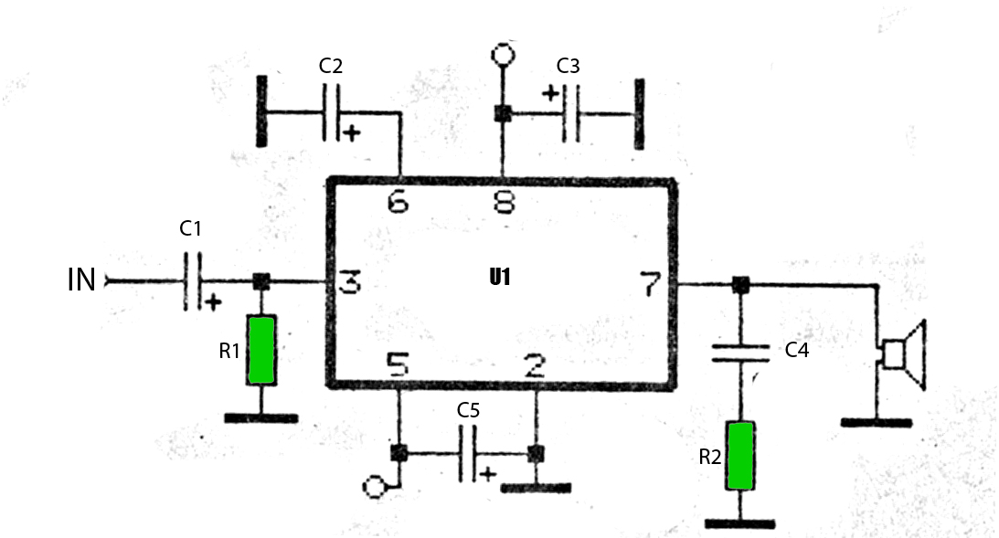
The Tiny Audio Amplifier kit is a good choice for battery operation. It is based on LM386 IC. Power supply - 6 - 12 VDC. Output power - 1 W, 8 Ohm. The quiescent power drain is only 24...
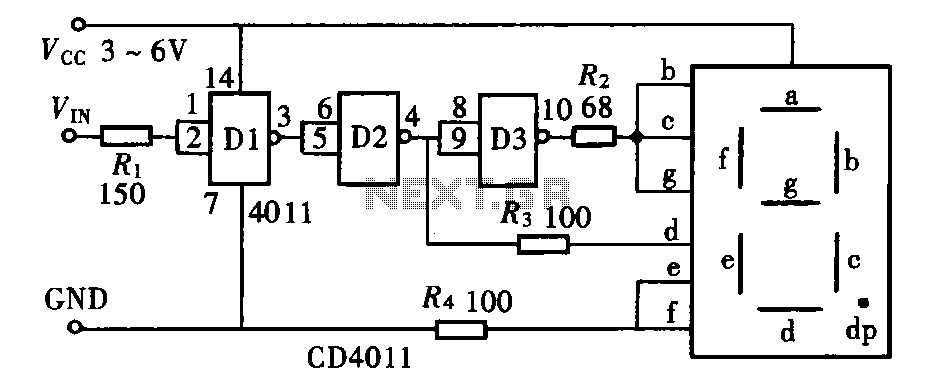
The door circuit logic pen text display can take many forms, utilizing various logic gates such as inverters, NAND gates, NOR gates, and others. A logical pen, exemplified by the NAND gate CD4011, can be used in conjunction with...
The timing control circuit is a sequential circuit that allows for sequential timed control of two switches. The control time can be adjusted from a few seconds to several tens of seconds. If mechanical control is applied for reciprocating...
If you want to try a higher voltage with your pedals, try this simple and easy voltage doubler circuit which uses an ICL7660 CMOS Voltage Converter Chip. I have found that JFETs such as the J201 sound much better...
It is advisable to enclose this circuit in a box and label each LED with numbers from 1 to 6. When switch S1 is momentarily pressed, one of the six LEDs will illuminate, with the number corresponding to the...