
get on the blinkm bus with a blinkm cylon

The circuit design incorporates the Arduino as the main controller interfacing with the BlinkMs through an I2C bus. The I2C bus consists of two primary lines: SDA for data transmission and SCL for clock signals. The Arduino operates as the bus master, managing communication with the BlinkMs, which are configured as slave devices. Power is supplied through a +5V line, and a ground connection is established for proper operation of the I2C network.
The wiring is facilitated using ribbon cables and IDC connectors, which provide a clean and organized method for connecting multiple devices. The use of 8-wire ribbon cable allows for easy expansion while ensuring that the necessary connections for power and ground are included. The IDC connectors are crimped onto the ribbon cable, allowing for straightforward connection to the BlinkMs. Each BlinkM is configured with a unique I2C address, enabling the Arduino to control them individually.
In the Arduino code, the BlinkM_setRGB() function allows for immediate color changes, while the BlinkM_fadeToRGB() function enables smooth transitions between colors. The implementation of rotary encoders allows for interactive control of the RGB values, providing a hands-on experience for users. The design emphasizes durability and ease of use, making it suitable for environments where children are likely to interact with the device. Overall, this project showcases the versatility of BlinkMs and the simplicity of I2C communication in controlling multiple RGB LEDs in an engaging and visually appealing manner.BlinkMs are a lot of fun by themselves, but they`re also little network devices, each having its own address on an I2C network. Here`s where I think BlinkM can really shine since it makes controlling multiple RGB LEDs pretty easy.
For Maker Faire, I wanted to show off this facet by having a single Arduino control a dozen or so BlinkMs on a single I2C bus. The result is shown in the little video below. Controlling several RGB LEDs is no small task, BlinkM makes it easier and I wanted something for Maker Faire that demonstrated how simple controlling a dozen or so RGB LEDs could be. But I also wanted something that was eye-catching from a distance and robust enough for kids to play with.
Since I`ve done some Cylon stuff before, a BlinkM version of that idea could be interesting and eye-catching. I had also been building my own rotary encoders and I figured a rotary encoder could be built that was pretty cheap and yet sturdy enough for thousands of kids to play with.
A pretty simple schematic. Arduino is at the heart of things, of course. It`s a good brain for a task like this. There are two main facets to this project: dealing all these BlinkMs and making huge rotary encoder knobs. BlinkMs are I2C devices. There can be up to 127 different devices on an I2C network. 1 An I2C network or bus consists of two wires: SDA & SCL. SDA is a bidirectional data line and SCL is a clock driven by the bus master . In this case, Arduino is the bus master and BlinkMs are all I2C slave devices. The other two wires needed by I2C devices is power (+5V) and ground (gnd). While I2C networks were not originally designed to be more than a few inches long, most I2C devices can work on I2C buses several meters in length.
In this case, the total length of the I2C cable is about 1 meter (1 yard). The simple two-wire nature (four if counting power) of I2C makes wiring things up pretty simple: run a single multi-wire cable and tap off wherever you want to put a device. In this case, regular ribbon cable and IDC connectors were used. The smallest IDC connectors that work with BlinkMs are the 2-row x 4-position kind. This calls for an 8-wire ribbon cable, so half of the wires in cable aren`t used. The IDC connectors are crimp on, so place the connector where you want it on the ribbon cable and crimp it down.
Then just plug the BlinkM into the IDC connector. Each BlinkM has to have its I2C address set so it can be addressed uniquely. For this project, 13 BlinkMs were used, addressed from 10 to 22. The BlinkMMulti Arduino sketch in the BlinkM example code zip ( browse it here ) makes short work of addressing a handful of BlinkMs: insert BlinkM, type in new address, remove BlinkM, repeat. Below is the relevant parts in the Arduino sketch for controlling BlinkMs. If you notice, there`s only two lines of code needed to control 13 RGB LEDs. The rest of the logic is for doing the Cylon-like back-n-forth. The BlinkM_setRGB() tells a BlinkM to go to a color immediately, while the BlinkM_fadeToRGB() tells a BlinkM to fade to a color over a period of time set by a previous call to BlinkM_setFadeSpeed() .
#define num_blinkms 13 #define blinkm_start_addr 10 byte curr_blinkm = 0; int incdec = 1; // only +1 or -1 while( 1 ) { [get r, g, b values from rotary encoders] byte blinkm_addr = blinkm_start_addr + curr_blinkm; BlinkM_setRGB( blinkm_addr, r, g, b ); // set to color BlinkM_fadeToRGB( blinkm_addr, 0, 0, 0); // fade to black // prepare to move to the next cylon eye element curr_blinkm = curr_blinkm + incdec; if( incdec = 1 && curr_blinkm = num_blinkms-1 ) incdec = -1; else if( incdec = -1 && curr_blinkm = 0 ) incdec = 1; } } For this project, I wanted a device that wasn`t an absolute mapping of position to color amount. I didn`t want a strict teaching device, but more of a fun color exploratory toy, able to be spun like mad by kids.
Rotary encoders are used to measure rotational amount and direct 🔗 External reference
Related Circuits
The MAX34446 data logger for power supplies is capable of monitoring voltages for overvoltage and undervoltage conditions, as well as overcurrent and overtemperature situations. The device continuously checks user-programmable thresholds. The MAX34446 is an advanced monitoring solution designed for power...
Read the generic sound level from an electret microphone. Several schematics utilize NPN transistors that yield an inverted output (~5V when quiet, ~0V when loud, with linear operation in between). However, a non-inverted output is desired, where a super...
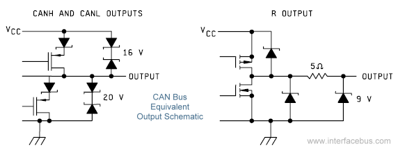
The Controller Area Network (CAN) Interface is a balanced (differential) two-wire interface that operates over Shielded Twisted Pair (STP), Unshielded Twisted Pair (UTP), or ribbon cable. Each node in the network utilizes a male 9-pin D connector. The bit...
The PCI Express (PCIe) bus defines the electrical, topology, and protocol aspects of a point-to-point serial interface over copper wire or optical fiber. In addition to the Physical Layer, the PCI Express specification also covers the Transaction Layer and...
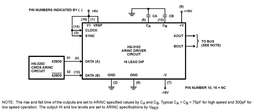
The HS-3182 is a monolithic dielectrically isolated bipolar differential line driver designed to meet the specifications of ARINC 429. This device is intended to be used with a companion chip, the HS-3282 CMOS ARINC Bus Interface Circuit, which provides...
This is the most simple phone busy indicator is possible with only three parts. Connect the circuit so that the green light illuminates when the line is free. If the receiver than the hook, the green LED light is...