
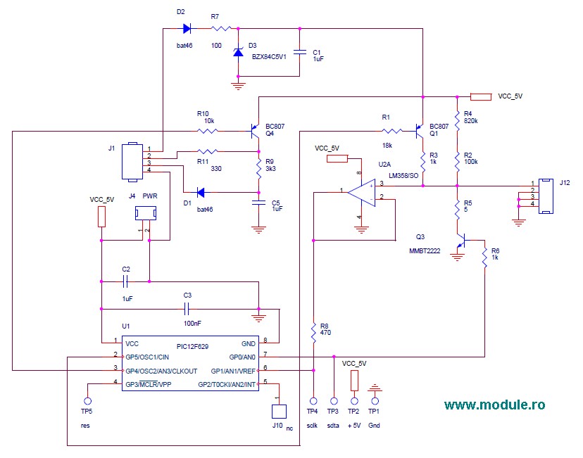
CAN Bus Interface I/O Schematic

The Controller Area Network (CAN) Interface is designed for robust communication in automotive and industrial applications. It employs a differential signaling method, which enhances noise immunity and allows for reliable data transmission over long distances. The use of twisted pairs, whether shielded or unshielded, further reduces electromagnetic interference, making it suitable for environments with significant electrical noise.
The interface operates using a male 9-pin D connector, which provides a standardized connection point for nodes within the network. The NRZ encoding scheme, supplemented by bit-stuffing, ensures that the data stream maintains a sufficient number of transitions for synchronization, which is critical for the reliable reception of data.
In terms of data rates, the CAN interface supports a wide range, from a minimum of 10 kbps to a maximum of 1 Mbps. The requirement for all modules to support a minimum of 20 kbps ensures compatibility and interoperability within the system. The relationship between cable length and data rate is significant; as the data rate increases, the maximum allowable cable length decreases. This characteristic necessitates careful planning when designing a CAN network, as it directly impacts the overall system performance.
To ensure signal integrity and minimize reflections, termination resistors are employed at both ends of the cable. These resistors match the characteristic impedance of the cable, which is typically around 120 ohms for CAN networks. Proper termination is essential to prevent data corruption and maintain communication reliability, especially in long cable runs.
The CAN interface's architecture allows for multiple nodes to communicate over the same bus, facilitating a multi-master setup where any node can initiate communication. This flexibility makes the CAN interface a preferred choice for distributed control systems, enhancing both efficiency and scalability in various applications.The CAN Interface is a Balanced (differential) 2-wire interface running over either a Shielded Twisted Pair (STP), Un-shielded Twisted Pair (UTP), or Ribbon cable. Each node uses a Male 9-pin D connector. The Bit Encoding used is: Non Return to Zero (NRZ) encoding (with bit-stuffing) for data communication on a differential two wire bus.
A number of different data rates are defined, with 1Mbps (Bits per second) being the top end, and 10kbps the minimum rate. All modules must support 20kbps. Cable length depends on the data rate used. Normally all the devices in a system transfer uniform and fixed bit-rates. The maximum line length is 1Km, 40 meters at 1Mbps. Termination resistors are used at each end of the cable. 🔗 External reference
Related Circuits
A modified Hartley oscillator can be utilized to attract new friends or serve as a replacement doorbell. The modified Hartley oscillator is a type of LC oscillator that uses an inductor-capacitor (LC) circuit to generate a continuous wave signal. This...
This circuit should only be attempted by individuals with a strong understanding of electronic devices. It is connected to a main power source (220V) and poses a risk of high electrical shock. This circuit operates at a mains voltage of...
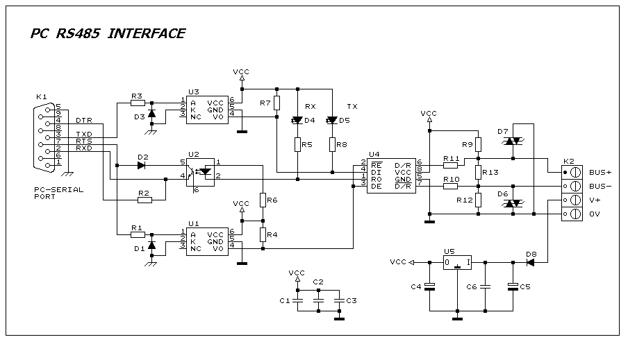
This interface circuit provides electrically isolated RS485 communication interface to the PC serial port. The isolation circuit protects the PC from direct connection to hazardous voltages. More: Figure 1 shows the circuit diagram of RS485 interface. Connector K1 is...

The hardware design for USB is quite minimal, which is advantageous. However, it quickly becomes apparent that the simplicity of the hardware design leads to complex communication and control software, which will be explored further in the theory and...
Dunlop Cry Baby Wah Wah Schematic. It is challenging to replicate the Cry Baby sound due to its unique characteristics. The Dunlop Cry Baby Wah Wah pedal is renowned for its distinctive tonal qualities and is a staple in many...
Unlike most surface-mounted device (SMD) resistors, SMD ceramic capacitors do not have their values marked. To determine the value of these capacitors, a capacitance meter is required. SMD ceramic capacitors are widely used in modern electronic circuits due to their...