
gps tracker project gps module jp module lcd dispaly
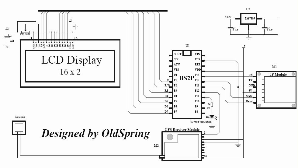
The project involves assembling various components, including the GPS module, microcontroller, and display, according to the provided schematic. After connecting the components, the code must be uploaded to the microcontroller for the system to function correctly. The GPS module outputs several data strings per second, including the essential RMC string, which provides the necessary positional information. The standard output rate is 4800 baud. The GPS module operates at 3V serial levels, which can be directly connected to the USART receive input on a PIC microcontroller. Configuring the USART to 4800 baud, with 8 data bits and 1 stop bit, allows for the reception of each character, which the code subsequently processes.
To successfully create a GPS tracking module, knowledge in several areas is essential. This includes understanding microcontroller programming, interfacing with serial communication protocols, and familiarity with GPS technology and its data formats. Students should also be adept at reading datasheets for components and troubleshooting potential issues during assembly and coding. Building a GPS module from scratch is a complex task that typically requires advanced skills and access to specialized equipment. It is advisable to utilize commercial GPS modules to simplify the development process while still achieving the desired functionality.A GPS tracker demonstration program with data logging capacity. It uses BasicStamp 2P (also you can use PIC chip) to interface with a GPS Module, JP Module and 16x2 LCD display. Sample code used is standard PBasic 2. 5 ( It can be changed to PicBasic or PicBasic Pro very easy). It can record GPS data to a MMC/SD card with latitude and longitude information. The data can be processed from Google Map at the website:. If you have Google Earth installed, the data also can be processed into a KML file (Google earth data file format) at the website: hi. u know what. ur project would be very helpful to me. coz we have been given the same project for our final year. but the problem is. i have been told to make the module of GPS myself. now can you pz let me know as to what all things may be necessary to study to make this possible. and whethr it is possible to be made on our own. plz reply soon. thanx. tc I think I have already posted all of information ( including manufactures and parts datasheet) for this project.
You can follow the project schematic put every parts togather, load the code to MCU. It should work. hi. u know what. ur project would be very helpful to me. coz we have been given the same project for our final year. but the problem is. i have been told to make the module of GPS myself. now can you pz let me know as to what all things may be necessary to study to make this possible. and whethr it is possible to be made on our own. plz reply soon. thanx. tc What do you have at your disposal In all likelihood you do not have the capability to build it yourself without using a GPS module. The 2GHz satellite signal is far beyond the ability of many engineers, never mind students, even with the appropriate ICs in hand.
Unless you have a $10K+ prototyping system capable of double sided plate through PCBs and are capable and willing to solder 0. 5mm pitch 100 pin ICs for 5-10 prototype runs to work out the bugs do not even bother. All GPS receivers that I have used will output several strings each second. All you need to do is apply power to the GPS receiver and the data strings start being sent. One of those is the RMC string which tells you all you usually need for position. The usual rate is 4800 baud. If you can connect to the 3 V serial level from the GPS, that can be connected directly to the USART receive input on a PIC.
If you set the USART to 4800 baud, 8 bits, 1 stop bit, it should receive each character, and then the code takes each character from the USART. 🔗 External reference
Related Circuits
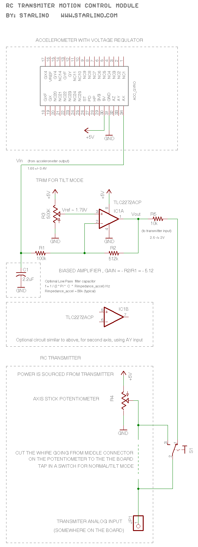
The RC transmitter utilizes a potentiometer for each axis, functioning as a voltage divider that outputs a voltage of 0.5V, with the middle position corresponding to 2.5V. This voltage is sent to the analog input, which is converted into...
The voltage regulator circuit was constructed using the LM317T, a three-terminal regulator. A heatsink was utilized to cool the LM317T. The output voltage can be set anywhere in the range of 1.5 volts to 30 volts; however, for this...
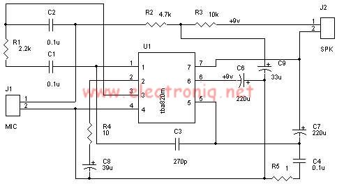
A very simple audio amplifier circuit can be designed using the TBA820M audio amplifier integrated circuit with just a few electronic components. This audio amplifier project features a high gain that allows for the detection of sounds underwater. The...
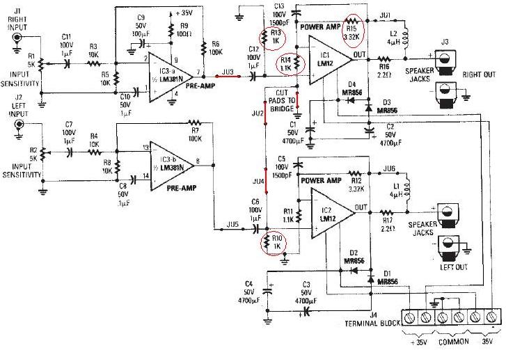
The LM12 audio amplifier circuit is designed to deliver high output power for 8 ohm or 4 ohm load impedances. The maximum output power provided by the LM12 audio amplifier is approximately 60 watts for a 4 ohm load...

A unified thermometric controller that can be programmed with simple scripts, integrating the "classic" thermometer/controller pair. You can build a variety of simple machines with the same hardware and a different script: a charting thermometer, a vending machine that...
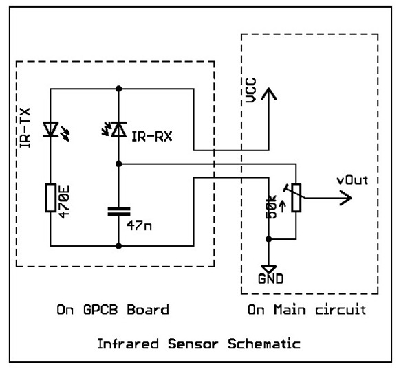
Overview: This tutorial demonstrates the creation of a simple infrared sensor module designed to detect reflecting surfaces. This sensor is capable of identifying reflective materials such as silver or white strips, as well as serving applications in obstacle detection...
Warning: include(partials/cookie-banner.php): Failed to open stream: Permission denied in /var/www/html/nextgr/view-circuit.php on line 713
Warning: include(): Failed opening 'partials/cookie-banner.php' for inclusion (include_path='.:/usr/share/php') in /var/www/html/nextgr/view-circuit.php on line 713