
dm projects
The voltage regulator circuit utilizing the LM317T is a versatile design that allows for adjustable output voltage through the careful selection of resistors R1 and R2. The LM317T is a popular choice for many electronic projects due to its ability to maintain a stable output voltage despite variations in input voltage and load conditions. The inclusion of a heatsink ensures that the regulator operates within safe temperature limits, enhancing reliability.
The bridge rectifier's role is crucial as it converts AC input into a stable DC output, which is necessary for the LM317T to function correctly. Protection diodes are essential in safeguarding the regulator and associated components from potential damage due to reverse currents, which may occur under fault conditions. The design of the resistor network for the LED displays is equally important, as it ensures that the current through the LEDs is limited to prevent damage while providing adequate brightness for visibility.
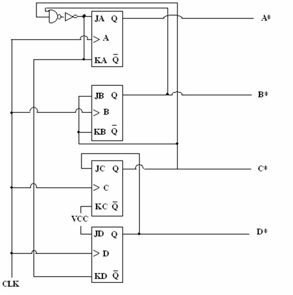
The counter design employing the 74LS163 chips demonstrates a clear understanding of digital logic principles. The cascading of counters allows for counting beyond the limits of a single counter, effectively creating a two-digit decimal counter. The use of NAND gates for feedback and control signals illustrates a practical application of combinational logic in sequential circuits.
The traffic controller design showcases the integration of digital logic with practical applications in traffic management. The JK flip-flops provide a robust method for creating state changes in the system, allowing for pedestrian interaction to enhance safety. The careful routing of signals and the implementation of the pedestrian request feature indicate a thoughtful approach to circuit design, ensuring that all aspects of traffic control are addressed. Overall, this project exemplifies the intersection of analog and digital circuit design principles, leading to a functional and efficient traffic control system.The voltage regulator circuit was constructed using the LM317T, 3 terminal regulator. A heatsink was utilized to cool down the LM317T. The output voltage can be set to anywhere in the range of 1. 5 volts to 30 volts. However, for our application we needed a 2. 5 volt output voltage. The selection of the desired output voltage comes with choosing app ropriate resistance values for R1 and R2. The use of a potentiometer for resister R2 allowed calibration of the desired output voltage. A bridge rectifier was used to receive the AC or DC input. Protection diodes were implemented to prevent the capacitors discharge from running back into the regulator in the event of abnormal operating conditions such as a sudden short circuit on the input or the output or a back emf from the inductive load. The resistor used for R1 was chosen to be 250 ohms making the voltage drop across it to about 1. 25V. This becomes the reference voltage of the regulator. Whatever current is flowing through R1 is also flowing through R2 and thus the sum of the voltage drops across R1 and R2 are the output voltage seen.
This project had two experimental steps that eventually led into the development of a traffic controller. The first approach involved designing a counter that would count to fifty-nine. This would later serve as the interval between changes in the traffic light states. This circuit design was achieved by using two 74LS163 counters. The first counter had the task of counting up to nine while the second counter had the task of counting up to five only after the first counter`s had cycled through one time.
To integrate these two counters, the first counter`s logical nine was NANDed and routed back to its clear pin to be reset to repeat another cycle. This output coming from this NAND gate was then inverted and then by routed into the second counters clock input where a cycle (0 9) can be detected by the second counter.
When second counter detects this signal, it then increments itself by one. The second counter increments by one until it reaches it`s logical five, where there after, logical five is sent through an NAND gate and routed back into it`s clear to make the chip reset itself at the end of one complete cycle (0 5). To display the results of this 1 minute counter, the outputs of the two counters were then routed to two 7447 decoders.
The counters results were then outputted from the decoders (7 outputs per decoder) into a pair of resister networks (330 ohm) consisting of 7 resistors per network. The pair of 7 out puts were then routed from each resistor network into a pair of common anode 7 segment LED displays (one LED per resistor network).
The LED`s provided 7 diodes per display piece that when powered, displayed the corresponding counting from 0 59). The second experimental step involved designing the controller system for the traffic controller. To design this control system, a pair of positive edge JK flip-flops were used (74LS109A). The circuit was designed with a pedestrian request as well which allows a pedestrian to request the lights to all turn red for one minute.
The circuit was connected as follows: For flip-flop A, Q was routed into flip-flop B`s K input and was also NORed with QNOT which then lead into the J input of flip-flop A. Pin K was connected to ground as it was active low. QNOT was routed to flip-flop B`s J as well as to two separate NAND gates where it was NANDed with flip-flop B`s Q as well as flip-flop B`s QNOT.
These two NAND gates essentially became our outputs to the red and green led. The way in which the pedestrian request was integrated into this circuit was by connecting a single dip switch with a 1k resistor up to Vcc where it would then lead to an NOR gate to be NORed with the result of the Q and QNOT that it itself was producing. This project had three experimental steps that eventually led into the development of an adding and multiplying de
🔗 External reference
Related Circuits
In 1991, there was significant interest in a specific display technology that was difficult to find locally and expensive to import. Currently, this technology has become widely available and is considered obsolete due to the affordability and accessibility of...

This project involves the DiSEqC-Tester, which is designed to test DiSEqC switches utilizing protocols 1.0 and 1.1. The device is compatible with DiSEqC switches that follow protocols 2.0 and 2.1, as they maintain backward compatibility with the earlier versions....
A tiny speedometer/trip computer was constructed using an Atmel ATTiny2313 microcontroller and an HD44780-compatible character LCD display, along with a reed switch and magnets. This device measured the speed of a soapbox derby cart by attaching a permanent magnet...
This program includes circuit design CAD, simulation, and auto-routing PC layout. PSPICE is also utilized at Unisys, which offers more capabilities but costs six times as much and requires annual renewal. With these requirements and others in mind, a...
Nowadays, every institution requires automation. As part of college automation, a project has been developed titled "Voice Interactive System for College Automation." This project enables users to quickly access student attendance and marks through a telephone line without the...
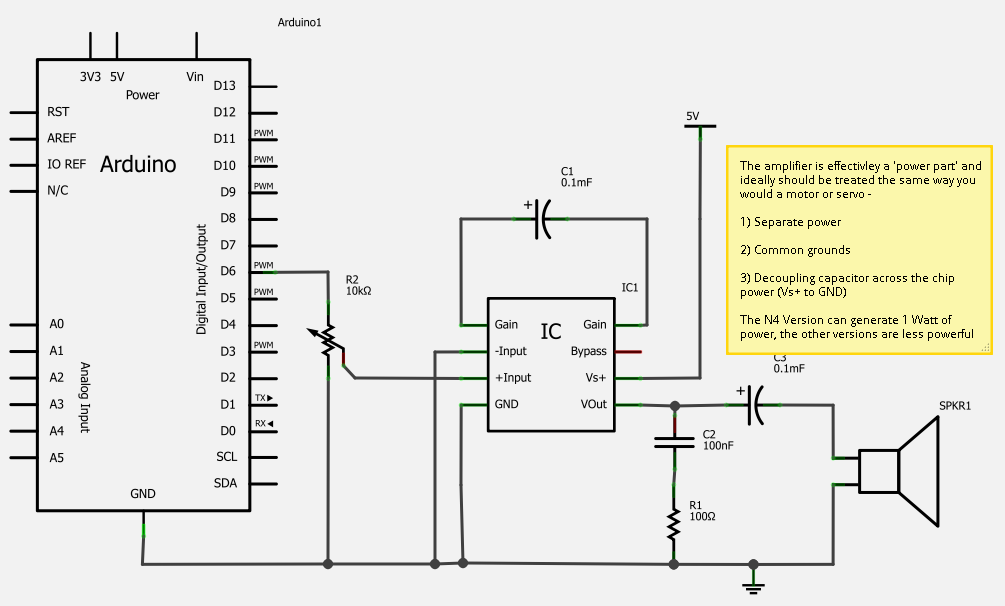
A simple solution for enhancing sound output from a microcontroller is the LM386 series of amplifier chips, which provide high-quality audio for under one dollar. These chips can be used to create a functional MP3 docking station and serve...