
Gray Tube Replication 91
The project involves assembling a circuit that utilizes Teflon-coated coaxial cable, a material known for its excellent dielectric properties and high-temperature resistance. This type of cable is particularly advantageous in RF (radio frequency) applications due to its low loss and ability to maintain signal integrity over longer distances.
In this circuit, the coaxial cable will serve as the primary transmission line, connecting various components while minimizing signal degradation. The choice of Teflon coating enhances the cable's durability and makes it suitable for environments where temperature fluctuations may occur.
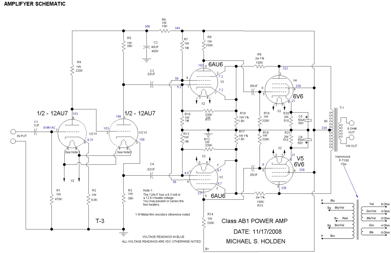
The schematic should include a detailed layout of the circuit, indicating the connections between the coaxial cable and other components such as resistors, capacitors, and any active devices like transistors or operational amplifiers. It is essential to specify the impedance of the coaxial cable used, typically 50 or 75 ohms, depending on the application.
Additionally, the circuit should incorporate proper grounding techniques to reduce noise and interference, ensuring optimal performance. The layout must also consider the physical arrangement of components to minimize inductance and capacitance that could affect high-frequency signals.
Overall, the assembly process will require careful attention to detail, particularly in soldering techniques and ensuring that all connections are secure to prevent signal loss. Proper testing and validation of the circuit will be necessary to confirm that it meets the desired specifications and functions as intended.Originally Posted by Spokane1 I have just about all of the parts needed for a first run. Mr. Dollard says he used Teflon coated coax, which is.. 🔗 External reference
Related Circuits
Inquiry regarding the suitability of a design for a first tube amplifier build, along with a request for recommendations on suitable components. The inquiry pertains to the construction of a tube amplifier, which is a type of audio amplifier that...
It is unlikely that the device was designed to be powered by a 9V battery, as they are not very robust. The battery life is typically under 2 hours when using an alkaline battery. The power requirements of electronic devices...
Stereo tube amplifier circuit built with 5 power tubes: 6SQ7-GT, 6V6-GT, and 5Y3-GT. This circuit generates up to 4 watts of audio output per channel. The stereo tube amplifier circuit utilizes a combination of five power tubes, specifically the 6SQ7-GT,...
Electron tubes, their operation, early history, types including triodes, tetrodes, beam power tubes, pentodes, combination tubes, ionization (gas-filled) tubes, display tubes, and microwave tubes, as well as a comparison with semiconductors. This site is dedicated to all types of...
The +/- 3 dB point for the treble is approximately 2.5 kHz, with a boost/cut of about 12 dB at 10 kHz. It may be necessary to check the wiring or component values. Access to a signal generator is...
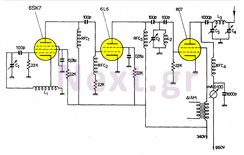
This transmitter operates in the shortwave range from 6 MHz to 22 MHz. Coil L1 serves as the shortwave oscillating coil for the 6SA7 vacuum tube and is commercially available. Capacitor C1 is a variable capacitor with a capacitance...