
Groovewatt a DIY Vacuum Tube (Valve) RIAA Phono Preamplifier Project
 RIAA Phono Preamplifier Project")
The phono preamp circuit design is structured around a modular architecture, allowing for easy adjustments and component substitutions. The symmetrical SRPP (Shunt Regulated Push-Pull) configuration in the input stage is instrumental in achieving high linearity and low distortion. This topology provides a balanced input signal, which is critical for maintaining fidelity in audio applications. The passive equalization network, which follows the input stage, is designed to accurately replicate the RIAA curve, ensuring that the frequency response adheres to industry standards for vinyl playback.
The second stage, which mirrors the SRPP configuration, enhances the overall gain while maintaining signal integrity. Direct coupling to the cathode follower stage minimizes signal loss and preserves the dynamic range of the audio signal. The choice of Gold Pin JJ ECC83S tubes is significant, as these components are known for their low noise characteristics and high gain, making them suitable for high-fidelity audio applications. The alternative use of ECC803S tubes offers a cost-effective option while still delivering commendable performance.
The cathode follower stage is designed to present a low output impedance, making it compatible with a wide range of line stage preamps and power amplifiers. This characteristic is particularly beneficial when driving long cables or low-impedance inputs, which can often introduce signal degradation in less robust designs. The ability to drive high-sensitivity headphones is an added advantage, broadening the versatility of the preamp.
The project emphasizes the importance of component selection, particularly in the equalization network. Resistor and capacitor tolerances play a critical role in maintaining the accuracy of the RIAA response. It is recommended to use high-quality audio-grade components to ensure optimal performance. The design allows for minor deviations in component values, but it is essential to keep these changes within limits that do not significantly affect audio fidelity.
In summary, this phono preamp project exemplifies a meticulous approach to audio circuit design, with a focus on achieving high performance through careful component selection and circuit topology. The result is a versatile and high-quality audio preamplifier suitable for a range of applications, particularly in vinyl playback scenarios.This is a project that I always wanted to do, but managed to put off for a long time. It has been over a year in the doing. Partly because there are so many good phono preamps in existence and I was slightly concerned that it was beyond my design skills. It took over a year to get it up to my satisfaction. There were several iterations and lots of frustration along the way. My goal was to make a preamp that would not embarrass the builder with inferior performance. I used a number of commercial products for comparison. My thought was why bother to design and build something that was already available for a lower cost. As it turns out, it was not as inexpensive nor un-complicated as I first hoped. I wanted response within 0. 5 dBV of the RIAA curve, low distortion, and a signal to noise of about -90 dBV. The first two were easy, the signal to noise was not. I did a lot of research on the RIAA curve and the various problems that are inherent in phono preamps. I tried active, passive and a combination of active and passive equalizations. All work and all have positive features and all have negative features. I tried several configurations and tube types. The final design uses things I am familiar with. The input stage is a symmetrical SRPP. It feeds the passive equalization network. The second stage is nearly identical with the first and is direct coupled to the third stage which is a cathode follower.
I eventually used Gold Pin JJ ECC83S in both of the SRPP stages and half of a ECC81 (12AT7) for the cathode follower. Gain is sufficient at 45 dB for me to use a high output MC cartridge (I use a Dynavector 10X5 with an alternate of a Denon DL-110) to drive a passive volume control to feed a pair of Oddblocks.
The initial design tried using other tubes but none had sufficient gain in the SRPP configuration. The performance of JJ ECC803S tubes is nearly as good as the Gold Pin JJ ECC83S and is a lower cost option. Be sure to ask for matched pairs though. The third stage is almost optional as the output impedance of the SRPP is low enough (14K) to drive most line stage preamps and directly to power amps with a 100K passive volume control.
I added that stage so that it would be possible to drive long cables and following equipment that had low impedance inputs. It is actually possible to drive some high sensitivity 300 ohm impedance headphones to sufficient volume.
The preamp is designed for moving magnet (MM) and high output moving coil (MC) cartridges with a signal level over 2. 0 mV. I believe the best way to handle the output from a low output MC cartridge is with a transformer so no attempt was made to handle them with this project.
On the schematics I show a way to get as much as 3 dB more gain, but at a slight expense of more noise. The name of the project came from another DIYer (Thanks, Shane). I asked for suggestions and his was the best. He won an "Oddwatt T-shirt" for the idea. Warning: This project uses dangerous and potentially lethal voltage levels. If you are unfamiliar or do not feel comfortable working with the voltages involved, I highly recommend that you do not attempt the project.
The actual design is almost modular in that both gain stages are nearly identical. Circuit values in the equalization section are the exact ones needed and in the case of the resistors you will probably need to series a few smaller ones to get the needed values. Some deviation is possible and while it will alter the RIAA response, the actual amount of deviation will most likely be inaudible.
I found 11k resistors at Parts Express which in place of the 10. 9k will not mess up compliance with the RIAA curve much. The capacitors should have tolerances as close as you can get. I used a capacitor meter to select mine from a large batch of samples. With both the resistors and capacitors, the closer to the values the better the performance will be. I used all audio grade (in this 🔗 External reference
Related Circuits
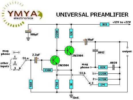
Most audio amplifier systems must have preamplifiers with many different characteristics. These include high-gain linear response for magnetic microphones, low-gain linear response for tuners, and high-gain RIAA equalization for magnetic phone cartridges. To meet this broad requirement, most amplifier...
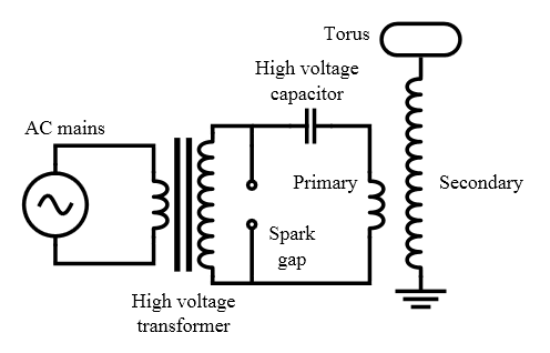
To create a full-scale Tesla Coil that produces at least 6 inches of sparks, also referred to as "artificial lightning." Current Status: The project was successful, with a complete full-scale, full power test conducted on Friday, July 15, 2011....
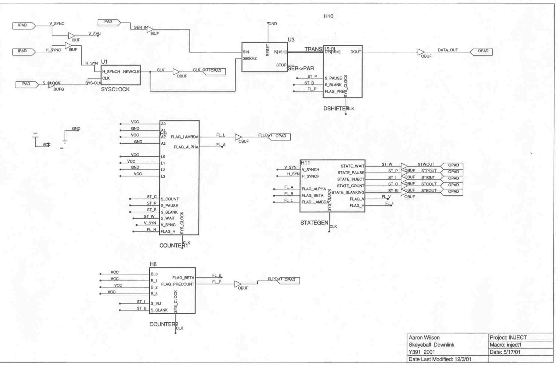
The Skeyeball project is an ongoing initiative within the Indiana University System Design Methods Laboratory, aimed at providing graduate and undergraduate students with opportunities to engage in embedded system design and implement various projects. The downlink segment of the...
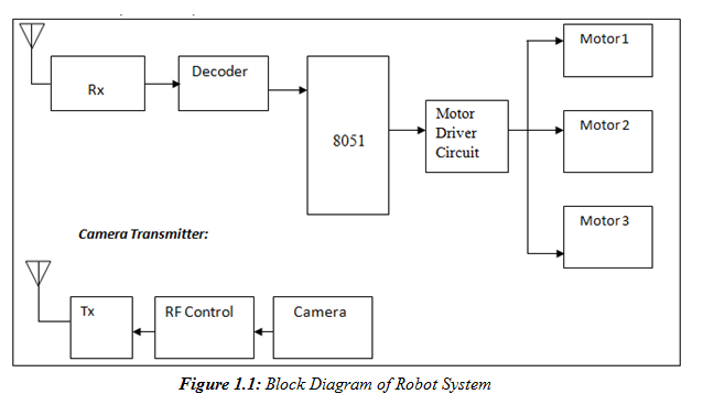
A prototype model of an agriculture-based robot has been developed to address the challenges faced by farmers who have traditionally relied on manual labor for cultivating their lands. The increasing urbanization has led to a shortage of labor, as...
A project called LED Flasher that sequentially flashes LEDs one by one. There is a query regarding the project, and any simple explanation would be greatly appreciated. A reference image or a link can be used for additional context. The...
The drawings and photos below are for an operating incline railway that was built by the London Model Railroad Group for its O scale model railway club located at London, Ontario, Canada. This is a single car model loosely...