
GSM Based Voting Machine System ECE Project Report
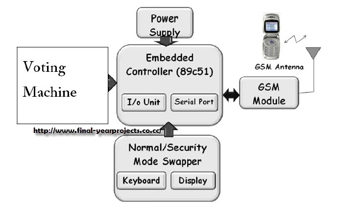
The GSM-based voting machine system is designed to streamline the voting process using mobile communication technology. The system is built around a microcontroller, which serves as the central processing unit. It interfaces with a GSM module that is responsible for sending SMS messages containing the votes cast by users. The GSM module communicates with the microcontroller through a serial interface, typically utilizing UART (Universal Asynchronous Receiver-Transmitter) for data transmission.
In Normal mode, the system restricts voting to authorized users within a specified local area. This is achieved through a user authentication mechanism, which may involve the use of unique identification numbers or passwords. The microcontroller processes the input from the voting machine, validates the user, and sends the vote via the GSM module.
In contrast, Security mode allows for a broader participation, where any registered voter from across the country can cast their vote. This mode may require additional security measures, such as encryption of the SMS data and validation of the sender's phone number to prevent unauthorized voting.
The voting machine is equipped with a user interface, which may include buttons for input and an LCD display to provide feedback to the user. The power supply unit ensures that the entire system operates reliably, providing the necessary voltage and current levels for the microcontroller and other components.
The block diagram of the system provides a visual representation of the interconnections between the components, illustrating how the microcontroller, GSM module, and voting machine interact. The circuit diagram included in the report details the electrical connections and component specifications, serving as a valuable resource for students and engineers interested in replicating or modifying the system.
Overall, this GSM-based voting machine project exemplifies the integration of telecommunications and electronics, showcasing how modern technology can enhance democratic processes. The comprehensive documentation provided, including programming details, enables users to understand and implement the system effectively.This is a good Electronics & communication project on GSM Based Voting Machine System which uses AT commands to sens SMS through Microcontroller. The project has 2 modes viz. Normal mode and Security mode. In normal mode an authorized person of a local area can vote and security mode is any one from the whole country can vote.
The project require a GSM module, a voting machine connected to Microcontroller, power supply etc. You can also Subscribe to FINAL YEAR PROJECT`S by Email for more such Projects and Seminar. The above image shows the block diagram of GSM Based Voting Machine System and its components. The report contains the circuit diagram and microcontroller programming for students. You can use this report for your reference and study. 🔗 External reference
Related Circuits
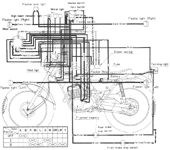
The following image illustrates the Yamaha 175 Wiring Diagram (CT2 and CT3 model) and Electrical System Schematic. It provides detailed information regarding the interconnection and wiring between electrical components of the motorcycle, including the battery, ground, headlight, taillight, horn,...
This technical note focuses on determining the system specifications of a CDMA receiver to establish practical specifications for a low noise amplifier and down converter. The design of a CDMA (Code Division Multiple Access) receiver necessitates a comprehensive understanding of...
This simple telephone switching system is designed by Dr. Mustafa Kemal Peker for training purposes. All responsibility belongs to the user. Schematic and circuit details are included. The telephone switching system designed for training purposes serves as an educational tool...
This article discusses the Gadgets, Gizmos, and Arduino (ATMega328). The content is straightforward and informative. The components mentioned in this article can enhance the understanding of the subject. For instance, readers can find and purchase components such as the...
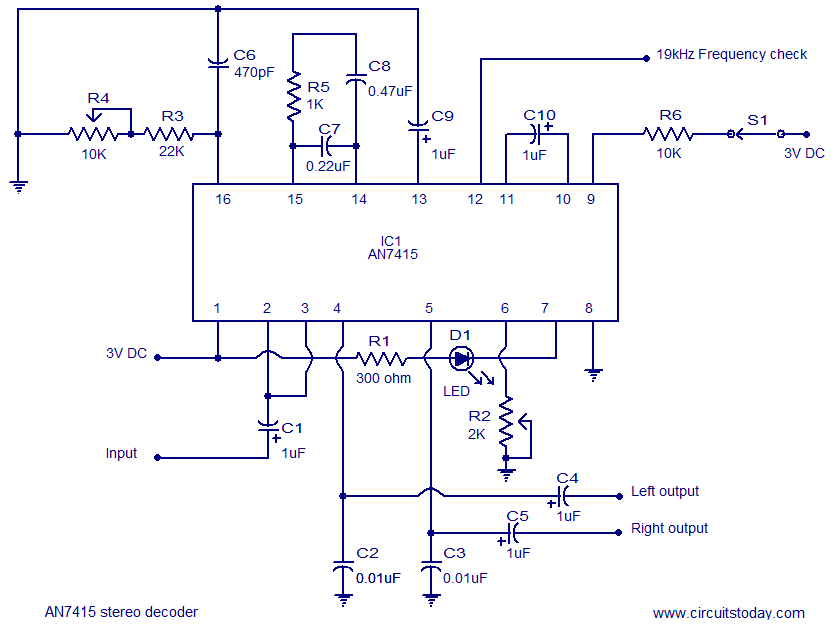
AN7415 based FM stereo demodulator circuit. 1.6 to 7V operating voltage range. High gain and low distortion. The AN7415 is a versatile integrated circuit designed for FM stereo demodulation applications. This circuit operates within a voltage range of 1.6 to...

A 4001 CMOS Quad NOR gate is configured as an astable multivibrator, which drives a simple differentiator and relay driver. Depending on the setting of S2, a delay of 5 to 30 seconds is generated. S2 and R1 through...
Warning: include(partials/cookie-banner.php): Failed to open stream: Permission denied in /var/www/html/nextgr/view-circuit.php on line 713
Warning: include(): Failed opening 'partials/cookie-banner.php' for inclusion (include_path='.:/usr/share/php') in /var/www/html/nextgr/view-circuit.php on line 713