
Yamaha Wiring System

The Yamaha 175 Wiring Diagram serves as a vital reference for understanding the electrical layout and interconnections within the motorcycle's system. The schematic highlights the essential components, including the battery, which supplies power to various electrical devices, and the ground, which provides a return path for current. The headlight and taillight circuits are crucial for visibility, while the horn serves as an important safety feature. The rectifier converts AC voltage from the flywheel magneto into DC voltage, essential for charging the battery and powering the electrical components.
The 2005 Yamaha DT125X electrical system showcases a more advanced setup with a CDI unit that enhances ignition timing and efficiency. The system's integration of a servomotor allows for precise control of engine functions, while the neutral switch ensures safe starting conditions. The inclusion of a rectifier/regulator is critical for maintaining battery voltage and preventing overcharging.
The Mikuni Carburetor Schematic provides insight into the carburetor's operation and the various components that facilitate fuel delivery and air mixture. Each part plays a specific role in ensuring optimal engine performance, emphasizing the importance of proper maintenance and tuning.
The Yamaha TDM850's electrical system is designed for comprehensive troubleshooting, with detailed guidelines covering various components and their functions. The presence of multiple safety switches, such as the sidestand and neutral switches, highlights the importance of safety in motorcycle operation.
The Yamaha Vino 125S and Virago Electric Starter systems illustrate the evolution of motorcycle electrical systems, incorporating features that enhance user convenience and safety. The Virago's starting system exemplifies modern safety protocols, ensuring that the motorcycle cannot be started under unsafe conditions.
Overall, these schematics and diagrams provide essential information for technicians, enabling effective maintenance and repair of Yamaha motorcycles. Understanding the interconnections and functions of each component is crucial for ensuring reliable performance and safety on the road.The following picture shows theYamaha 175Wiring Diagram(CT2 and CT3 model) andElectrical SystemSchematic. Herein you get detail information regarding the interconnection and wiring between electrical parts and components of the motorcycle such as battery, ground, headlight, taillight, horn, rectifier, brake, flywheel magneto, etc.
Generally the 20 05 Yamaha DT125X electrical system consists of CDI unit, servomotor, battery, fuse, neutral switch, thermo unit, rectifier/regulator, ignition coil and main switch. You can find detail and complete2005 Yamaha DT125X Wiring Diagram here on the last page of the service manual.
The followingMikuniCarburetorSchematicandDiagramapply for Yamaha DT250 and DT350series. The carburetor consists of following parts: pilot jet, float needle seat assembly, washer, o-ring, needle jet set bolt, needle jet washer, main jet, gasket, cover bolt, float, float lever arm, float pivot pin, float bowl gasket, float bowl, plate, float bowl screw, needle jet, throttle slide, clip, spring seat, throttle slide return spring, clip, carburetor cap, cable adjuster, etc. Find detaildiagram and schematics of Yamaha DT250|350 Mikuni Carburetorhere TheYamaha TDM850is a Dual Sports or Adventure Sports motorcycle produced by Yamaha Motor Company of Japan, that first came out in 1991.
The following wiring diagram andelectrical system troubleshooting manual actually part of 1996 Yamaha TDM850 service manual. Herein you will find detail information regardingelectrical system troubleshooting guideline and wiring diagram harness schematic of TDM850 which covers discussion on electrical components, switch inspection, ignition systemcircuit diagram and troubleshooting, electric starter system, starter motor, charging system, lighting system check, signal system wiring diagram, throttle position sensor self diagnosis.
The 1996 TDM850 electrical components consists of igniter unit, starting circuit cut-off relay, rectifier/regulator, main switch, thermo switch, thermo unit, flasher relay, starter relay, fuse box, battery, rear brake switch, sidestand switch, neutral switch, and ignition coil. The following electrical system schematic shows the Yamaha Vino 125SWiring Diagram. The electrical system consists of battery, CDI unit, carburetor heater, sidestand switch, horn, rectifier/regulator, ignition coil, rear brake light switch, starter relay, etc.
The Yamaha Virago Electric Startersystem consists of starter motor, starter solenoid, starter circuit cutoff relay, starter cutout relay, sidestand relay, sidestand switch, neutral switch, starter button and related wiring. When the starter button is pressed, it engages the solenoid switch which closes the circuit. Electric current then flows from the battery to the starter motor. When the engine stop switch and the main switch are turned ON, the engine can only be started if the transmission is in NEUTRAL, or if the clutch lever is pulled in (transmission in gear) and the sidestand is up.
If the above conditions are not met, the starting circuit is disabled and the starter will not operate. Get the detail schematic ofYamaha Virago Electric Starter Circuitand Wiring Diagram here. 🔗 External reference
Related Circuits
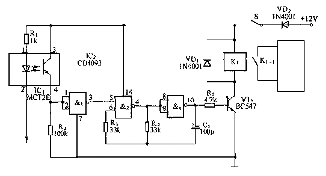
An anti-theft car audio system circuit is depicted, powered by a 12V DC supply from the car battery. Upon closing switch S1, the light-emitting diode in optocoupler IC1 activates, causing the phototransistor to conduct. This results in a high-level...
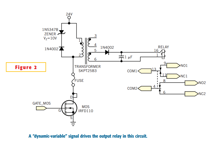
Many electronic-control systems have digital outputs that use transistors. One method of improving the security in these outputs is to use an oscillating signal to represent a logic-high state instead of a fixed voltage level. This type of signal,...
A PING Ultrasonic Range Finder is designed to create a system capable of detecting and measuring the distance (in millimeters) to the nearest object in front of the sensor. It functions similarly to a digital measuring tape; the user...
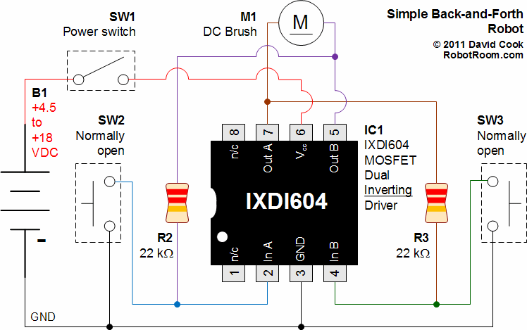
A schematic that illustrates the connections to the Clare IXDI404PI chip, which serves as both the control unit and power driver for a DIY Back-And-Forth robot. The Clare IXDI404PI chip is a dual-channel, high-speed, high-current driver designed for driving inductive...
Before building amateur rockets, model rockets were constructed and flown, starting in the summer of 1971. Seeking a greater challenge, the following year, the decision was made to build rockets entirely from scratch. The first rocket was simple and...
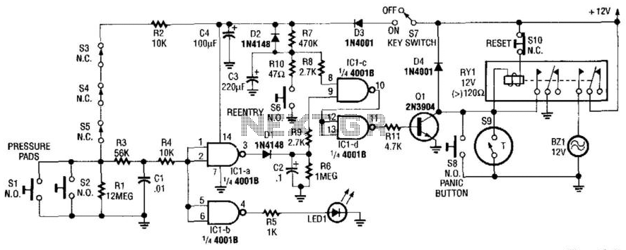
This alarm circuit activates when switches S1 through S5 are engaged. This action illuminates LED1 and triggers transistor Q1 through integrated circuits IC1C and IC1D. Relay RY1 is configured for self-latching. Switch S10 is utilized for resetting the circuit....