
Guitar OmniDrive effect

The distortion pedal described operates using a series of interconnected analog circuits that allow for a wide range of tonal shaping and distortion effects. The pre-amplifier section is designed to amplify the input signal while offering a switchable treble boost, enhancing higher frequencies for a brighter sound. This is particularly useful for achieving clarity in distorted tones.
The switchable low-pass filter serves to attenuate higher frequencies, allowing for a warmer, smoother distortion that can be tailored to the user's preference. This feature is crucial for creating a variety of tonal characteristics, from classic rock sounds to heavier genres.
The inclusion of a switchable full-wave rectifier enables octave-up effects, which can add harmonic richness to the signal. This section is particularly valuable for creating unique sound textures that stand out in a mix.
The clipping stage is a vital component of the distortion pedal, featuring variable gain control and two distinct clipping modes. This allows the user to select between different distortion characteristics, whether they prefer a smooth overdrive or a more aggressive fuzz tone.
The rotary controls for drive, tone, blend, and volume provide intuitive user interaction, allowing for precise adjustments to the overall sound. The drive control adjusts the amount of distortion applied to the signal, while the tone control shapes the overall frequency response. The blend control allows for mixing between the clean and distorted signals, enabling a more dynamic range of sound. The volume control sets the output level of the pedal.
The additional scoop switch modifies the tone control circuit by cutting mid-range frequencies, catering to specific styles such as death metal, where a scooped mid-range is often desired.
For versatility in sound design, the suggestion to mount the clipping diodes via a 3.5mm miniature break jack allows users to experiment with different diode types, such as germanium or asymmetric diodes. This feature enhances the pedal's adaptability, enabling users to customize their distortion characteristics further.
Overall, the described distortion pedal combines essential elements of analog circuitry with user-friendly controls, making it suitable for a wide range of musical styles and preferences.This is a versatile distortion pedal. Think of it as analogue modelling, using analogue circuitry to model a wide range of analogue distortion devices. It includes the main elements found in the majority of distortion boxes. The unit comprises four sections: A pre-amplifier with switchable treble boost. A switchable low pass filter. A switchable full wave rectifier for octave-up effects. A clipping stage with variable gain and two clipping modes. These stages are combined with level and tone controls to allow emulation of most of the multi-stage overdrive and fuzz units. The rotary controls are drive, tone, blend and volume. The switches are treble boost, low-pass filter, octave up and distortion mode. I have also added an optional scoop switch to the tone control circuit. This cuts the mid-range and should be popular with death metal noise vandals. I suggest mounting the clipping diodes via a 3.5mm miniature break jack. That way you can insert little plugs with germanium diodes or asymmetric diodes or whatever in them. 🔗 External reference
Related Circuits

A cost-effective nickel-cadmium battery charger using the LM393, featuring the following characteristics: (1) It provides constant current charging interspersed with high current discharge. The charging current is approximately 300mA, while the discharge current increases with battery voltage, reaching nearly...
The integrated circuit (IC) generates various sound effects, with the output at Pin 3 amplified by a transistor. A 64-ohm loudspeaker can replace the 56-ohm resistor and 8-ohm loudspeaker. A two-pole, four-way switch controls the sound effects, with position...
This is a straightforward sound effect generator based on the single sound generator chip UM3561. The UM3561 can produce four types of sound effects. Its basic operation involves generating a sound signal, which is then delivered to a 2N3706...

This FM transmitter has a number of features, with a volume control to adjust the input level and a small, neat box to make it easier to attach to a guitar. The volume control is positioned at the end...
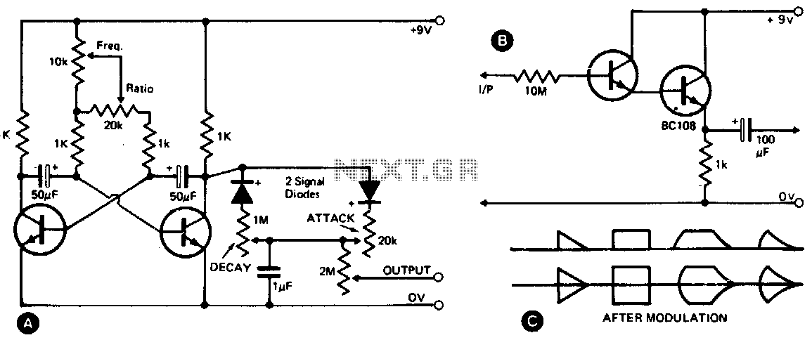
This waveshape generator functions as a slow-running oscillator with adjustable attack and decay times. It features a variable amplitude output, which is high impedance and can be controlled through a 2M potentiometer. Additionally, an add-on circuit is illustrated in...
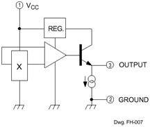
The Hall Effect sensor generates a voltage that is proportional to the strength of the magnetic field it detects. This sensor consists of a silicon layer with two electrodes on either side. In the absence of a magnetic field,...