
h bridge circuit
An H-bridge circuit is essential in applications requiring bidirectional control of DC motors. The configuration typically includes four switching elements, which can be either bipolar junction transistors (BJTs) or field-effect transistors (FETs). The arrangement of these transistors allows for two complementary paths for current to flow through the motor, enabling it to rotate in either direction based on the control signals applied to the gates or bases of the transistors.
The H-bridge operates by activating two diagonally opposite transistors while keeping the other two off, allowing current to flow through the motor in one direction. To reverse the motor's direction, the control signals are switched to turn off the first pair of transistors and turn on the other pair. This method of control provides a straightforward solution for applications such as robotics, where precise motor direction control is necessary.
It is crucial to select appropriate transistors that can handle the maximum current the motor may draw during operation. For small motors, standard transistors may suffice; however, for larger motors, higher-rated components or additional protective measures, such as heat sinks, may be required to prevent thermal damage. Additionally, implementing flyback diodes across the transistors can protect the circuit from voltage spikes generated when the motor is turned off, thus enhancing reliability.
In summary, the H-bridge circuit is a fundamental building block in motor control systems, providing an efficient means to manage motor direction with minimal complexity while requiring careful consideration of component ratings to ensure safe and reliable operation.An H bridge is a kind of circuit you use to control the direction (and sometimes speed) of an electric motor, using only a single polarity voltage (you need to reverse the way current flows in order to reverse the way the motor rolls). You have 4 transistors, wired as ON OFF switches. Two signal lines allow you to run the motor in one direction, w hen reversed, the motor runs in the other direction. It`s very straightforward to use and build, but be careful to use only small motors, as the currents drawn from the bigger types can burn your components. 🔗 External reference
Related Circuits
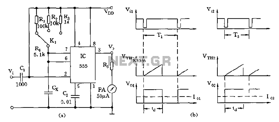
The circuit utilizes a 555 timer along with timing resistors R1 to R3 and a measured capacitance Cx to create a capacitance meter. The principle of capacitance measurement in a one-shot circuit is based on the relationship between the...
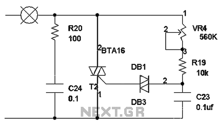
The TRIAC dimmer circuit diagram operates on the principle that a 220V lamp is controlled through the charging of capacitor C23 via resistors VR4 and R19. The charging time is influenced by the values of VR4 and R19, where...
This page is provided to the domain owner free by Sedo's Domain Parking. Disclaimer: The domain owner and Sedo maintain no relationship with third-party advertisers. References to any specific service or trademark are not controlled by Sedo or the...
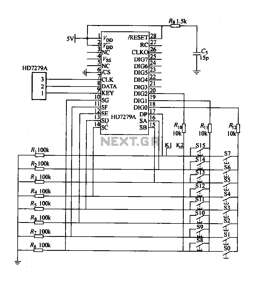
The design includes a front panel featuring buttons for setting 10 number keys (0-9), along with additional keys such as "Move Down," "Health," "Enter," "Recover," and a "Door Key," totaling 16 keys. The system also incorporates an interior door...
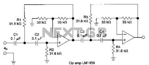
This circuit, which utilizes an LM1458 or a similar operational amplifier, functions as a fourth-order high-pass filter with a roll-off rate of 24 dB per octave. The resistor values Rx/R2 and RJRV can be adjusted to accommodate different cutoff...
The MP3 files (up to 65,536) are stored on a micro SD card. This embedded MP3 module is a universal and compact circuit (37 mm x 27 mm) designed for playing MP3 audio files. The MP3 module can be...