
555 monostable circuit is used as a table or capacitance resistance meter schematic
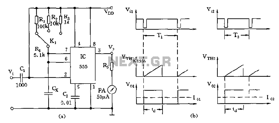
The circuit operates by initially charging the capacitor Cx through the resistors R1 to R3, which set the timing characteristics of the 555 timer in monostable mode. The output pulse width, td, is determined by the formula td = 1.1RCx, where R is the equivalent resistance seen by the capacitor during its charging phase. As the capacitor charges, the voltage across it rises until it reaches the threshold level of 2/3 Vdd, at which point the output of the 555 timer goes low, terminating the pulse. This duration of the pulse is directly related to the capacitance value, allowing for an indirect measurement of capacitance.
To utilize the circuit for resistance measurement, the measured resistance Rx can be connected in series with a fixed capacitor C. By adjusting the range change switch and recalibrating the meter, the circuit can accurately measure resistances. The output waveform can be visualized on an oscilloscope, displaying the pulse width corresponding to the capacitance or resistance being measured. The design is versatile, allowing for both capacitance and resistance measurements through minimal modifications, making it a valuable tool for electronics testing and diagnostics. As shown by 555 and the timing resistor R1 ~ R3 and measured capacitance Cx can be composed pointer capacitance meter, one-shot circuit capacitance measurement principle is the use Cx greater capacity, the greater the stability of the one-shot pulse temporarily that the voltage on Cx charge to the threshold level (2/3Vdd) the time required for longer. Due td 1.1RCx relationship, so when the input pulse triggers a fixed period, the output of the average amplitude of td (or Cx) is proportional to the relationship between the use of its amplitude of the ammeter to detect current flowing through the meter It reflects the size of the output pulse width td 555 size, which reflects the size of the capacity Cx.
If the circuit Cx exchanged for a fixed capacitance C, and the measured resistance Rx R will be placed in a position, through the range change switch and recalibration of the table, the table can be used as resistance measurements. Figure b its waveform.
Related Circuits
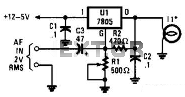
In the visible-light transmitter, a 7805 voltage regulator is configured in a variable-voltage setup, with an audio signal input to modulate the output voltage. The modulated output voltage is utilized to transmit information through an incandescent lamp. The visible-light transmitter...
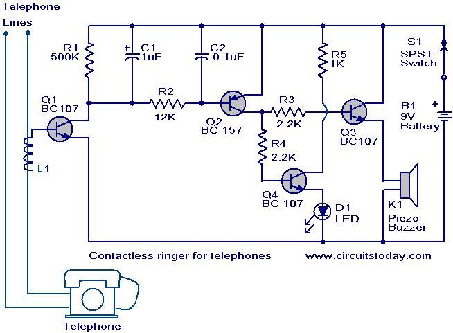
The contactless telephone ringer circuit is designed to produce an audible ring and a visual indication when a call is received. Its primary advantage lies in the absence of direct contact between the telephone line and the circuit, which...
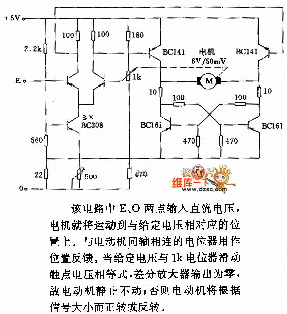
In the circuit, when E and O are input DC voltages, the motor moves to a position corresponding to the voltage. A potentiometer, coaxially connected to the motor, is used for position feedback. When the given voltage equals the...
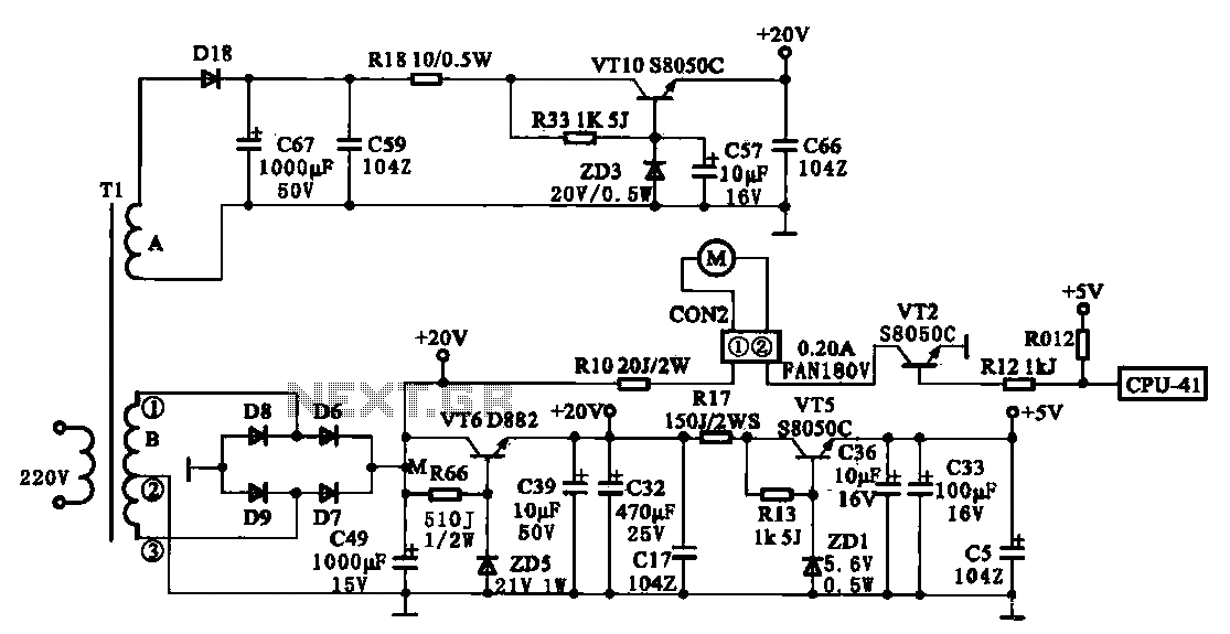
The JYC-22F type cooker low voltage power supply circuit is depicted. An AC 220 V power supply voltage is applied to a low-voltage transformer. The transformer has a primary winding (Tl) and two secondary windings (A and B), with...
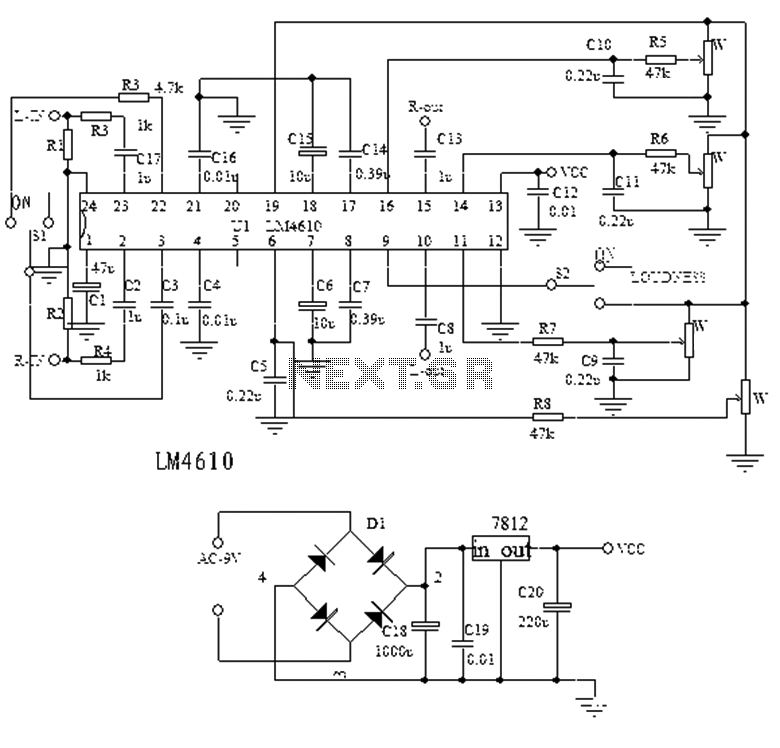
The LM4610 is a product from a US company, succeeding the LM1036, and represents a new class of high-end Hi-Fi tone integrated circuits (ICs). It serves as an ideal alternative to the LM1036, utilizing a two-channel DC voltage to...
The difference between these two ICs. A microcontroller is a specialized type of microprocessor designed to be self-sufficient and cost-effective, while a microprocessor is typically intended for general-purpose use, such as in personal computers (PCs). The microcontroller integrates several...
Warning: include(partials/cookie-banner.php): Failed to open stream: Permission denied in /var/www/html/nextgr/view-circuit.php on line 713
Warning: include(): Failed opening 'partials/cookie-banner.php' for inclusion (include_path='.:/usr/share/php') in /var/www/html/nextgr/view-circuit.php on line 713