
hardware control with computer
This closes the switch S1 and turns the LED1 ON. As the water continues to fill the tank, the LEDs2, 3 and 4 light up gradually. When the water is full, the base of the transistor BC148 is pulled high by the water and this saturates the transistor, turning the buzzer ON. The SPST switch has to be opened to turn the buzzer OFF. This circuit utilising a 555 timer IC can be used as an alarm system to prevent the theft of your luggage, burglars breaking into your house etc.
The alarms goes ON when a thin wire, usually as thin as a hair is broken. The circuit is straightforward. It uses a 555 IC wired as an astable multivibrator to produce a tone of frequency of about 1kHz which gives out a shrill noise to scare away the burglar. It has to placed making an angle of about 30 - 45 degrees to the ground. This makes the rain water to flow through it to the ground and prevents the alarm from going on due to the stored water on the sensor.
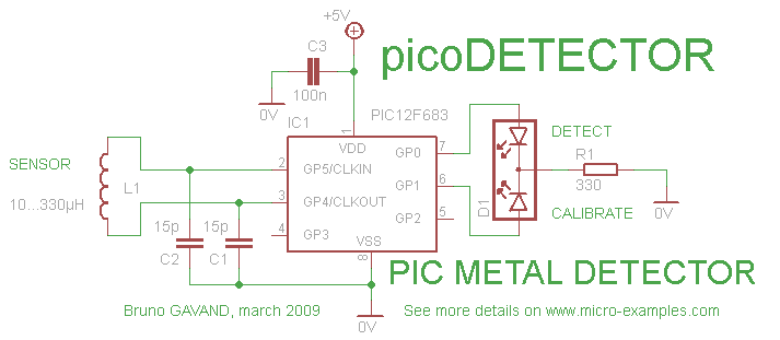
The metal used to make the sensor has to be aluminium and not copper. This is because copper forms a blue oxide on its layer on prolonged exposure to moisture and has to be cleaned regularly. The first IC (left) is wired to work around 1Hz. The 47uF capacitor is charged and discharged periodically and the voltage across it gradually increases and decreases periodically.
This circuit produces a sound similar to a factory siren. Uses a 555 timer Ic used as an astable multivibrator of a center frequency of about 300Hz. The frequency is controlled by the pin 5 of IC. When supply is turned on, the capacitor charges slowly and this alters the voltage on pin 5 of IC so the frequenct increases gradually. After the capacitor is fully charged, the frequency no longer increases. Now when the switch button siren control is pressed, the capacitor discharges and the siren frequency also decreases.
The presets VR1 and VR2 should be adjusted for optimum performance. This anti-theft alarm FM radio-control can be used with any vehicle having 6 - with the power supply 12 volt DC. The mini VHF, FM transmitter is installed in the vehicle at night when parked in the car porch or car park.
CXA1019 receiver with a single module IC-based FM radio, which is freely available on the market at reasonable prices, remains inside. The receiver is tuned to the frequency of the transmitter. When the transmitter is on and the signals are being received by FM radio receiver, no hissing is available at the output of the receiver.
Thus transistor T2 (BC548) does not hold. This results in the driver transistor T3 getting its relay forward base bias via 10k resistor R5 and the relay is energized. When an intruder tries to drive the car and takes a few meters from the driveway, the radio link between the car (transmitter) and alarm (receiver) is broken.
As a result FM radio module gene-rates hiss. Hissing AC signals are coupled to relay switching circ-uit via audio transformer. These AC signals are rectified and filtered by diode D1 and C8 capacitor and the resulting positive DC voltage provides a forward bias of transistor T2. Thus transistor T2 conducts, and pull the base of relay driver transistor T3 to ground level. The relay which disables the alarm connected via N / C relay is on. If, by chance, the intruder learns the wireless alarm transmitter and disconnect the battery, the alarm is still remote, because in the absence of the signal, the receiver continues to produce hissing noise at its output.
So the burglar alarm is foolproof and reliable. Brakelight bulb flasher This is basically a modified flash circuit on and off a bulb instead of LED. Use a 555 timer IC working as an astable multivibrator. The blink rat 🔗 External reference
Related Circuits

Stand-alone, 9V battery powered unit, three-level input selector, three-band tone control. This preamplifier was designed as a stand-alone portable unit. The described preamplifier is a compact, battery-operated device that operates on a 9V power supply, making it suitable for portable...
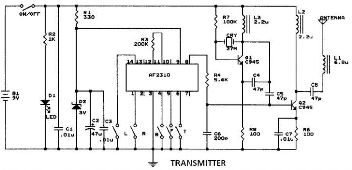
This circuit resembles that of a car radio-controlled toy with seven control functions: forward, forward-left, forward-right, backward, backward-left, backward-right, and stop. Additionally, this radio frequency circuit can be utilized for other electronic circuits that require a simple wireless motor...

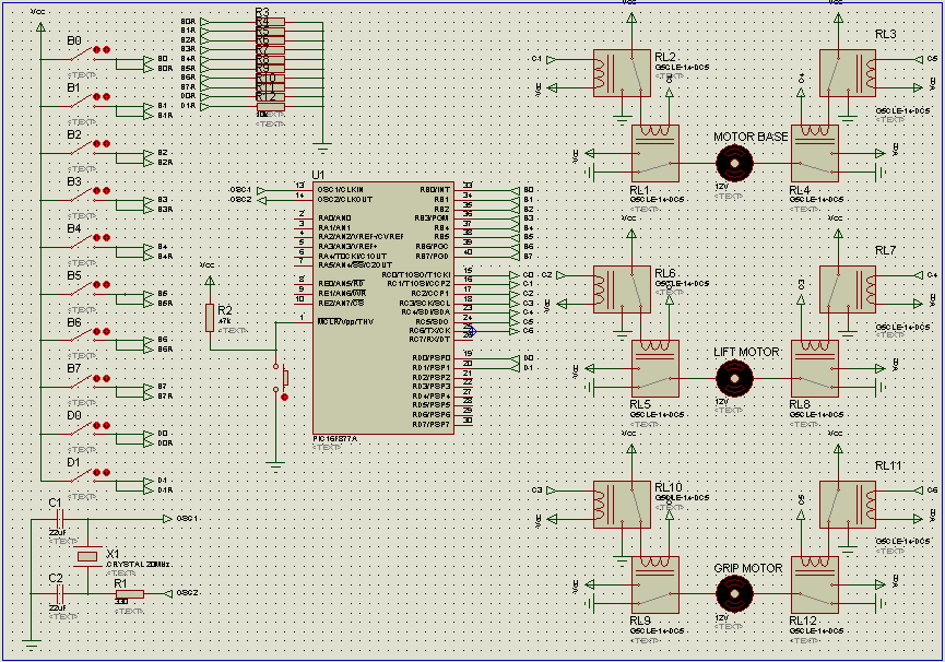
The convenience of selecting TV channels using your remote and then pointing the same remote to your Computer so that you can control the whole system using the single remote control. The Following functions can be done with PC...
This circuit illustrates the TDA1054 tone control stereo preamplifier circuit diagram. Features include the National Semiconductor LM35 integrated circuit, which utilizes semiconductor technology. The TDA1054 is a versatile integrated circuit designed for use in audio applications, particularly in tone control...
Iron the printed layout at a low heat setting until the ink adheres to the PCB. This process may take over an hour to complete. Afterward, remove the transparent paper. Next, submerge the PCB in Ferric Chloride solution until...
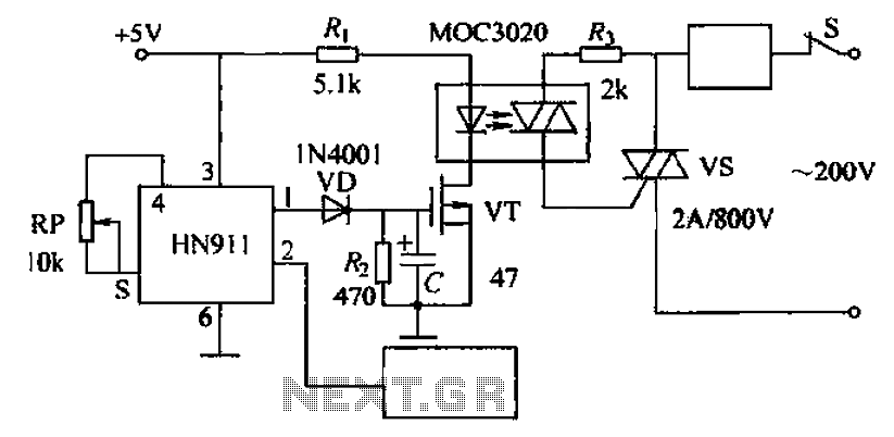
Automatic door control circuit diagram. It utilizes a pyroelectric infrared detection module, HN911, for human motion detection. A variable resistor (potentiometer) is used to adjust the delay time controlled by a transistor (VT). An optocoupler (MX: 3020) provides AC...