
Solar Powered Remote Control Surveilance

To create a printed circuit board (PCB) for a remote control car, the process begins with preparing a printed layout of the circuit design. The layout is then transferred onto the PCB using a method that involves applying heat. The heat should be set to a minimum to ensure that the ink adheres properly without damaging the board. This step may take upwards of an hour, requiring patience to ensure a successful transfer. Once the ink has sufficiently adhered, the transparent paper used for the transfer is carefully removed, revealing the printed circuit pattern.
Following the transfer process, the next critical step involves etching the PCB to remove unwanted copper. The PCB is submerged in a Ferric Chloride solution, a common etching agent that selectively dissolves exposed copper while leaving the ink-protected areas intact. It is crucial to monitor the etching process to ensure that the copper is completely dissolved without affecting the ink, which serves as a protective barrier for the desired circuit traces.
After the etching process is complete, the PCB requires mounting within the remote control car. To achieve a secure installation, holes need to be drilled into the chassis of the car. These holes will accommodate stands or supports for the PCB, ensuring that it remains stationary during operation. This stability is essential for the proper functioning of the circuit, as movement could lead to disconnections or damage. Finally, the circuit board is secured in place using screws, ensuring it is firmly attached to the remote control car's structure. This assembly process concludes the PCB preparation, allowing for the integration of the electronic components necessary for the remote control car's operation.Then iron the printed layout at minimum heat until the ink sticks to the PCB. It may take more than an hour to finish. Remove the transparent paper afterwards. 6) After that, submerge the PCB with Ferric Chloride Liquid until the expose copper is totally dissolved. Carefully make sure that the ink does not also dissolve so it can protect the wa nted copper underneath. 10)Drill some hole on the remote control car to put the PCB stands. This will prevent the circuit from moving. Screw the circuit onto the remote control car. 🔗 External reference
Related Circuits
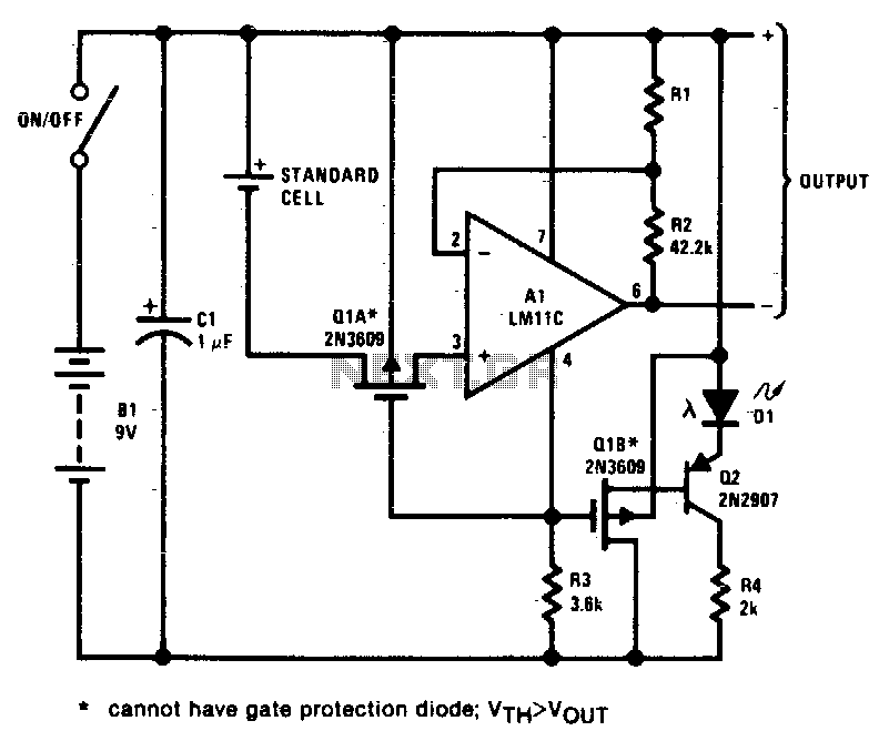
This circuit exhibits negligible loading and disconnects the cell in response to low supply voltage or an overload on the output. Additionally, the indicator diode turns off when the disconnect circuitry is activated. The circuit design incorporates a voltage monitoring...
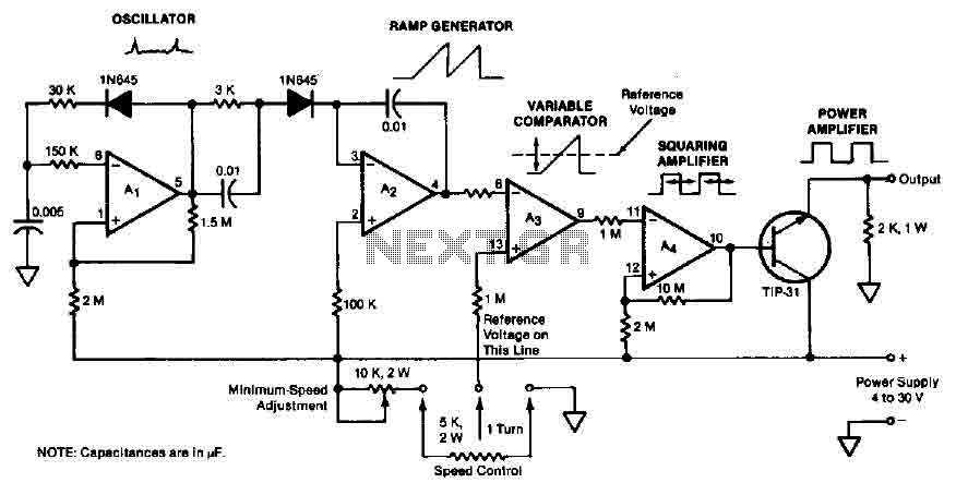
The quad operational amplifier circuit provides a pulse width modulation control ranging from 0 to 100 percent. The controller utilizes an LM3900 and operates with a single supply voltage between 4 to 30 V. A 1 kHz oscillator amplifier,...
The MAX5953A offers a straightforward, cost-effective, and comprehensive non-isolated power integrated circuit (IC) solution for Powered Devices (PD) in Power-over-Ethernet (PoE) systems. The MAX5953A is designed to facilitate the implementation of Power-over-Ethernet applications by providing an efficient means of...
It was discovered through experience why the 6V EQ-5 hand controller should not be connected to 12V by mistake. It only took about half a second to damage the hand controller. Upon inspection, it became clear that the large...
Even though the power was off, there was AC present at the handle plug, and a short circuit occurred. Upon disassembly, a blown transistor was discovered. An attempt was made to fix the issue, but after one month and...
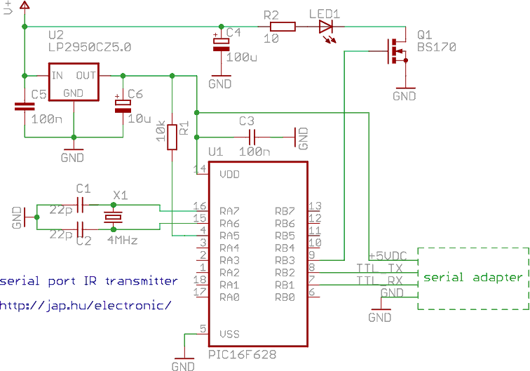
This is a programmable infrared (remote control) transmitter, which can be controlled from a PC serial port. It is capable of sending many remote control formats, including the Philips RC-5 standard. Exact formats with the timing parameter names are...