
Headphone Amplifier LM741
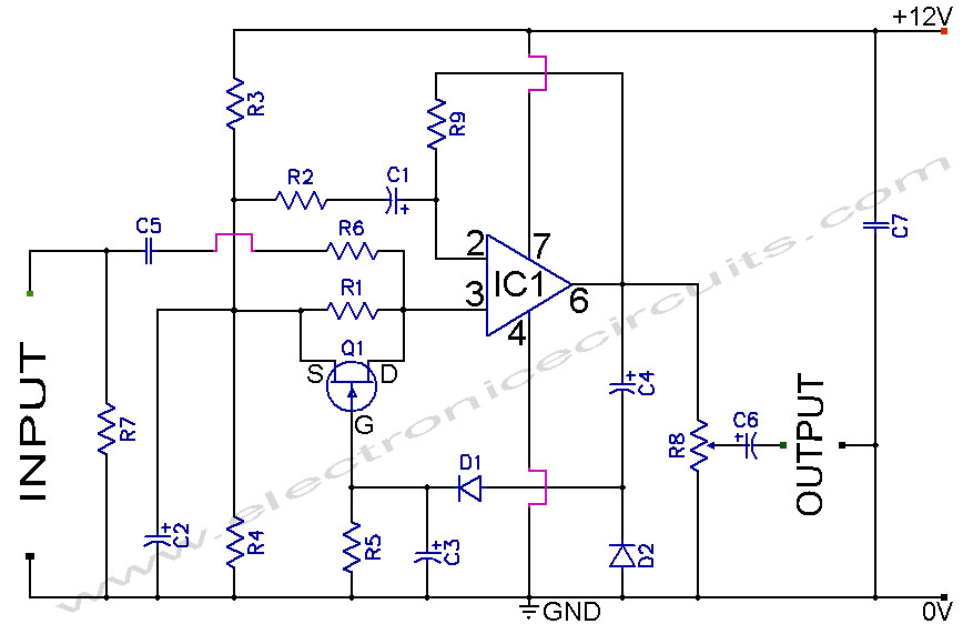
The headphone amplifier design described utilizes a supply voltage of 12 volts and is capable of delivering an output power of approximately 5 watts. The circuit architecture is based on an operational amplifier (op-amp) LM741, which provides the initial gain stage necessary for audio amplification. The output stage consists of a complementary push-pull configuration using transistors BD139 and BD140, which enhances the current driving capability of the amplifier.
The circuit is designed to be used primarily with headphones, although it can also drive small speakers. For stereo applications, the circuit can be duplicated, requiring two identical amplifier stages. The input signal is processed through a series of resistors (R1, R2, R3, R4, R5, R6, R7, R8, and R9) that set the gain and establish the input impedance, ensuring compatibility with various audio sources.
A critical component in this design is the 1000 µF capacitor (C5), which acts as a coupling capacitor in the output stage. It blocks any DC component from reaching the headphone or speaker, allowing only the AC audio signal to pass. This capacitor's value is chosen to provide a low-frequency cutoff at approximately 40 Hz when driving a load of 4 ohms, ensuring adequate bass response.
The circuit also incorporates a bass boost feature, which can be toggled to enhance low-frequency performance, making it suitable for various audio content. The overall current consumption is approximately 50 mA, which is efficient for portable applications. The design does not require additional heat sinking for the transistors when used with headphones, indicating that the power dissipation remains within safe limits under typical operating conditions.
The parts list includes resistors of various values, capacitors with specified voltage ratings, and diodes (1N4148) for signal protection. The use of a linear potentiometer (P1) allows for adjustable gain, providing flexibility in audio output levels. This headphone amplifier design is suitable for applications requiring a compact and efficient audio amplification solution.Here you will find a design for a headphone amplifier. The supply voltage is 12 volts. I have the circuit taken as 5 watt amplifier, but after a test showed that with a little speaker to the amplifier power was provided. It is better to connect to a headset. If you want stereo, you need double the amp build. The circuit is constructed with a 741, behind a balanced stair comprising a BD 139 and BD 140. The voltage for the speaker in the middle of this balance tapped using a blocking capacitor, which filters the amplified signal from DC.
This capacitor has a value of 1000 uF. This provides a lowest possible frequency of 40 Hz at 4 ?. For this example, the amplifier bass boost or bass control can be switched. The current consumption of the circuit is up to approximately 50 mA. The transistors do not need to be cooled when a headset is connected. Parts List R1, R3 = 10kW R2 = 100 kOhm R4 = 1 kOhm R5 = 15 kOhm R6, R7 = 2.2 kOhm R8, R9 = 1 ? P1 = 10kW lin C1 = 100 V ?F/16 C2 = 1 V ?F/16 C3 = 22 ?F/16 V C4 = 470 pF C5 = 1000 V ?F/16 D1, D2 = 1N4148 T1 = BD139/16 T2 = BD140/16 IC1 = LM 741
🔗 External reference
Related Circuits
Explore the power amplifier integrated circuit from National Semiconductor, the LM4780. What is noteworthy about this component is its very low harmonic distortion. Typically, manufacturers specify the maximum power of their products with a harmonic content of around 10%....
The amplifier circuit utilizes negative current feedback, which ensures that the load current is primarily influenced by the input signal rather than the loudspeaker's impedance. The inductor current from the loudspeaker generates a voltage across resistor R7, which is...
This circuit is designed to drive a low-power speaker using a sound effects module or a noise generator. It can also be utilized to create amplified speakers for computer use. The circuit amplifies the input signal by a factor...
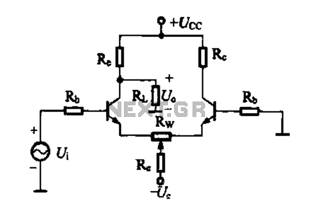
A differential amplifier circuit can be connected in four different ways, allowing for a comparison of their characteristics. The gain of the amplifier is equivalent to that of a single tube, with half the gain providing a high common-mode...
This is a simple circuit diagram for a 150W power amplifier. The circuit can be constructed without a printed circuit board (PCB). The power output ranges from 100W to 150W, depending on the power supply and the Darlington transistors...
A section of the operational amplifier's output signal is rectified using 1N4148 diodes, followed by filtering, and is then directed to the gate of the FET input shunting circuit. As the output voltage increases, additional input shunting occurs, which...