
HEADS OR TAILS GAME CIRCUIT
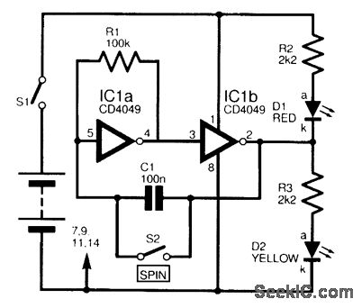
The electronic schematic for the coin toss simulator features a 4049 hex inverter IC, which consists of six independent inverters. In this design, two of the inverters (IC1a and IC1b) are employed in an astable multivibrator configuration. The astable operation is achieved by connecting resistors and capacitors to the input and feedback paths of the inverters, allowing for continuous oscillation.
The frequency of oscillation can be adjusted by varying the resistor and capacitor values in the circuit. This configuration results in a square wave output that drives the two LEDs, D1 and D2, connected to the outputs of IC1a and IC1b, respectively. The rapid switching of the outputs creates the illusion of both LEDs being lit simultaneously.
The SPIN switch S2 is a momentary push-button switch that, when pressed, interrupts the oscillation and latches the state of the LEDs. The LED that is lit at the moment of switch activation will remain on, simulating the result of a coin toss. Releasing the switch reconnects the circuit, allowing the astable oscillator to resume operation, thus reinitiating the alternating LED display.
To ensure reliable operation, bypass capacitors may be added to the power supply pins of the IC to filter out any noise. Additionally, current-limiting resistors should be included in series with the LEDs to prevent excessive current flow, which could damage the components. The circuit can be powered using a standard DC power supply or batteries, making it versatile for various applications, including board games and decision-making scenarios. Overall, this simple yet effective circuit provides a fun and engaging way to introduce randomness in gameplay.Designed to simulate by electronic means thetossing of a coin, the circuit is based upon a 4049 hex inverter IC, two of which are used. IC1a andIC1b are wired as an astable oscillator, which causes two LEDs D1 and D2 ‰ to alternate rapidly, at a frequency too high to be distinguished by thenaked eye.
Both LEDs, therefore, appear to be constantly illuminated. when the SPIN switch S2 is closed, this has the effect of freezing the display, and the LED, which was illuminated at the instantthat the switch was closed, will now be continuously alight. Opening the switch enables the oscillator once more. There is an equal chance of either LED lighting, and the circuit can be used in boardgames, for example, to choose which player will move first.
🔗 External reference
Related Circuits
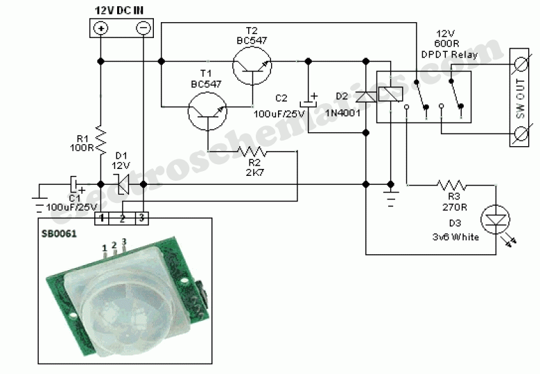
This circuit represents a general-purpose white LED security light equipped with a Passive Infrared (PIR) motion sensing mechanism. The core component of the circuit is the PIR sensor module SB0061, which is a pyroelectric sensor designed for human body...
This circuit is a compact +5V power supply that is beneficial for digital electronics experimentation. Inexpensive wall transformers with variable output voltage can be found at electronics shops and supermarkets. While these transformers are readily available, their voltage regulation...
This miniature audio amplifier provides an output of up to 250mW and can function as a final stage audio amplifier for radio sets. The schematic is straightforward, featuring one BC transistor. The described miniature audio amplifier is designed for efficient...
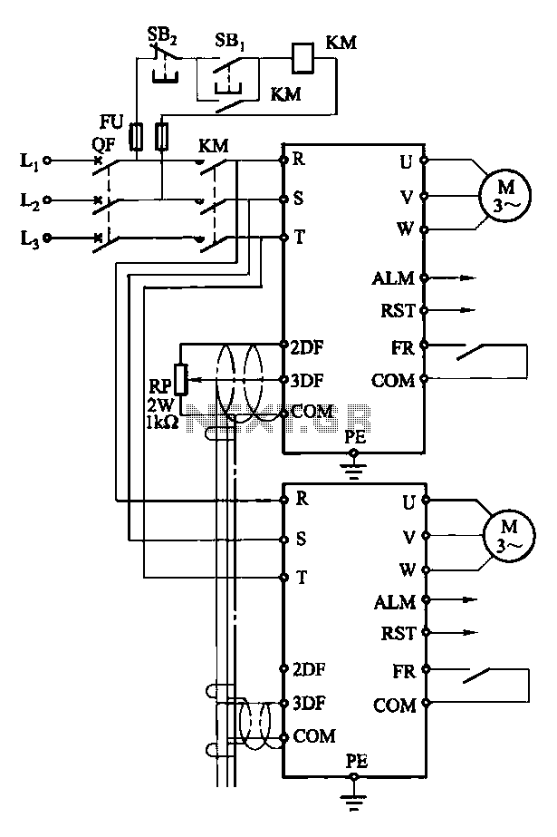
Each motor operates with an independent drive; however, only one frequency is utilized for a specific device. This setup employs a single RP potentiometer to control multiple motors in parallel. In this configuration, the circuit design allows for multiple motors to...
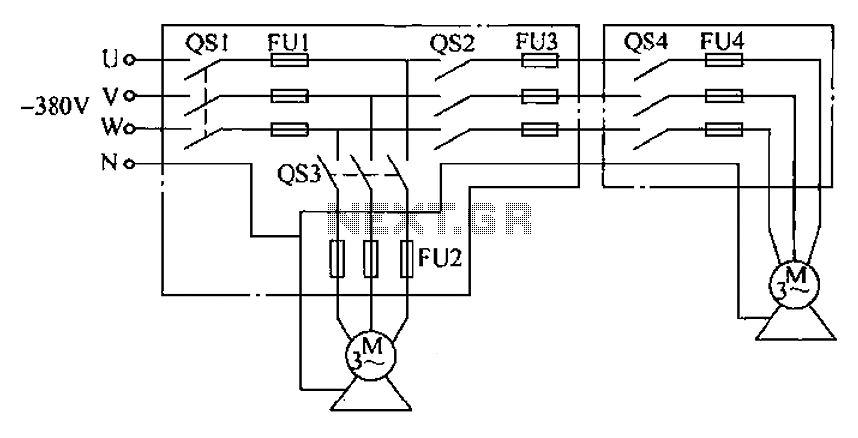
The agriculture and electrical power harrow plow power cord must consist of four rubber cables, with one core wire designated as the ground wire. The traction machine housing must be properly grounded. The two traction power machines are connected...
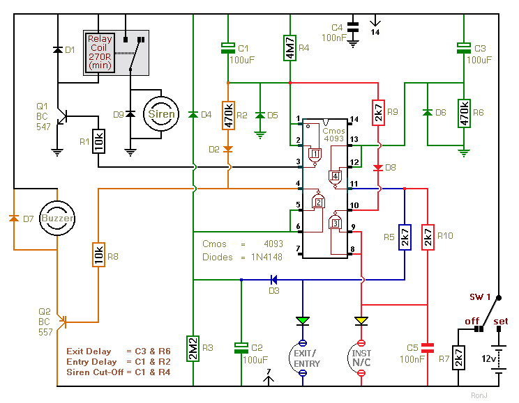
This two-zone alarm features automatic exit, entry, and siren cut-off timers. It was designed for the Beginner's Guide to CMOS Timers, providing a particularly detailed circuit description. An optional One-Time-Only module is available, which will deactivate the siren after...