
Electrical control circuit plow

In agricultural applications, ensuring the safety and reliability of electrical connections is paramount. The design of the power cord system for the harrow plow incorporates four rubber cables to withstand harsh environmental conditions typically found in farming settings. Among these cables, one is specifically designated as a ground wire, which is critical for preventing electrical shock hazards and ensuring the safe operation of the equipment.
The traction machine housing must be grounded effectively to facilitate the safe dissipation of any electrical faults. This is achieved by connecting the ground wire to a suitable grounding point, which could be an earth stake or a metal structure that is in contact with the ground.
The power distribution system utilizes a four-core cable branch box that connects to the farm's main power supply. This branch box serves as a central hub from which power is distributed to two separate traction power machines. Each machine is equipped with a dedicated power steering switch, allowing for independent operation while ensuring that both machines can be powered from a single source.
The sub-branch box is designed with three outlet holes to accommodate the cables leading to the traction machines. To maintain a secure connection and prevent accidental disconnection, the cables should be properly tied to these holes. This precaution is essential, especially in dynamic agricultural environments where movement and vibrations are common.
The power splitter box, constructed from durable metal, not only provides structural integrity but also ensures that the system remains grounded. This grounding is vital for protecting the equipment and operators from potential electrical hazards. The design of the splitter box allows for easy and convenient connections, facilitating quick setup and adjustments between the two tractor positions.
Finally, it is important to emphasize the necessity of promptly removing the power cord after use. This practice not only prevents potential tripping hazards but also minimizes the risk of damage to the cables or the equipment, thereby enhancing the longevity and reliability of the electrical system in agricultural operations.Agriculture and electrical power harrow plow power cord must be used four rubber cable, wherein a core wire as a ground wire, traction machine housing must be grounded. Two tra ction power machine is a quote from the same distribution box in the farms out of a four-core cable branch box to the power supply, power points as a branch box into two (respectively to the two tractor power steering switch on). As shown in Figure 8-9. In sub- branch box, cable outlet opening three holes, the cable leads should tie the hole to prevent the plug off on their own.
Power splitter box support such as metal, must be grounded and provided convenient connection of two tractor position. After use, the power cord should be promptly removed.
Related Circuits
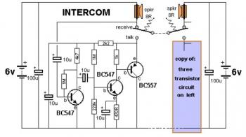
This is a two-station simple intercom circuit built using transistors and common 8-ohm mini speakers. The speaker functions as a microphone and generates sound, eliminating the need for a separate microphone in this intercom setup. The "press-to-talk" switches should...
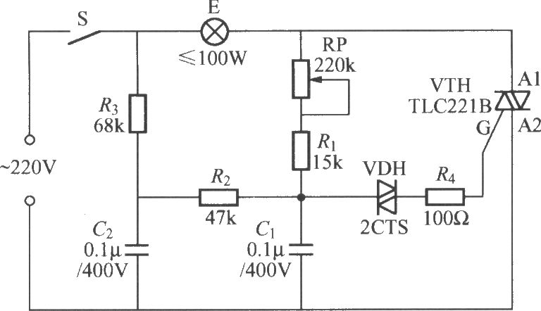
To address the lag and light transition issues, a Triac dimming light circuit featuring a dual time constant can be employed. This circuit enhances the resistor-capacitor network formed by R3 and C2. The reduced charge on capacitor C1 can...
The objective is to enhance information transmission by utilizing articles. Please contact us via email at [email protected] within 15 days if there are issues related to article content, copyright, or other concerns. Prompt action will be taken to resolve...
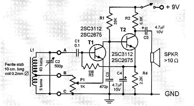
This is a compact and straightforward FM radio receiver capable of tuning into local FM stations. Its minimalistic design renders it suitable for various applications. The FM radio receiver circuit typically consists of several key components that work together to...
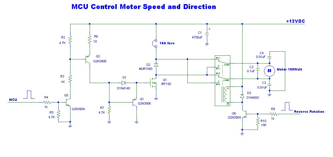
This is a power motor controller circuit designed for 12V applications. It utilizes a microcontroller unit (MCU) for signal control, operating at a high voltage level of approximately 3V. The circuit allows for the motor to be controlled to...
This project involves reading a thermistor using an Atmel ATtiny45 or ATMega168 microcontroller to control two fans for cooling a PC housed in a kitchen cabinet. A table is provided for converting the resistance of the BC1482 thermistor to...
Warning: include(partials/cookie-banner.php): Failed to open stream: Permission denied in /var/www/html/nextgr/view-circuit.php on line 713
Warning: include(): Failed opening 'partials/cookie-banner.php' for inclusion (include_path='.:/usr/share/php') in /var/www/html/nextgr/view-circuit.php on line 713