
Help me fix the noise in a FM receiver with AC/DC rectifier
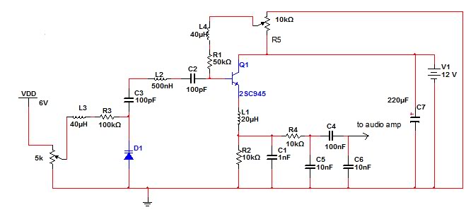
The FM receiver circuit operates by demodulating frequency-modulated signals to retrieve the original audio signal. The circuit typically consists of several key components: an antenna for signal reception, a radio frequency (RF) amplifier to boost the received signal, a mixer to convert the RF signal to an intermediate frequency (IF), and a demodulator to extract the audio information from the IF signal.
In this particular design, a 9V power supply is optimal, as it provides adequate voltage for the RF amplifier and other active components, ensuring stable performance and sufficient gain. The use of an AC/DC rectifier or a switch-mode power supply may introduce noise or ripple voltage that can adversely affect the sensitive components of the circuit, leading to degraded audio quality or loss of signal.
To enhance the performance of the FM receiver, it is advisable to include bypass capacitors near the power supply pins of the active components. This will help filter out high-frequency noise and stabilize the voltage supply. Additionally, careful layout considerations should be made to minimize interference, such as keeping the RF and audio sections physically separated and using shielded cables for the antenna.
Overall, the FM receiver circuit's performance is highly dependent on the quality of the power supply and the proper design of the circuit layout.The above circuit is fm receiver. when i used pin supply 9V, this circuit had quite nice performence. But when i used AC/DC rectifier or switch supply .. 🔗 External reference
Related Circuits
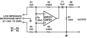
A simple but effective fixed gain transformerless microphone preamplifier circuit diagram is shown in the picture below. The circuit amplifies differential signals from low impedance microphones by 50 dB and has an input impedance of 2 kOhms. The OP27/37...
The tuned circuit consists of a variable capacitor and fixed air spaced coil. For the coil, wound between 10 and 20 turns of wire on an empty tube of around 1.5 inches diameter. The turns were spaced so that...
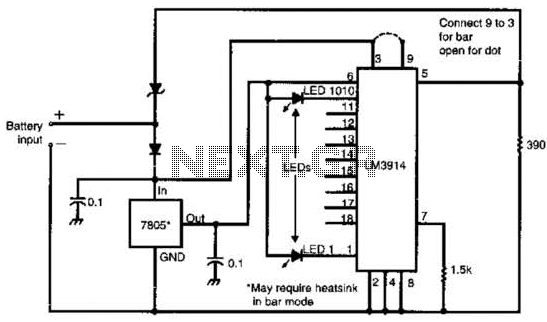
Many amateur receivers are equipped with an S meter that does not operate logarithmically. The proposed circuit is intended to enhance such receivers. Although integrated circuits like the CA3089 or CA3189 are not commonly used today, they play a...
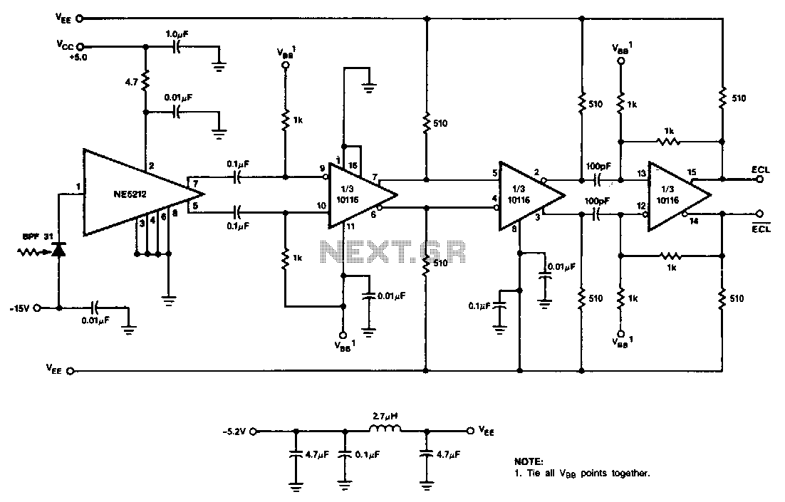
This receiver utilizes the NE5212, the Signetics 10116 ECL line receiver, and the Phillips/Amperex BPF31 pin diode. The circuit is a capacitor-coupled receiver that employs positive feedback in the final stage to introduce hysteresis. The level of hysteresis can...
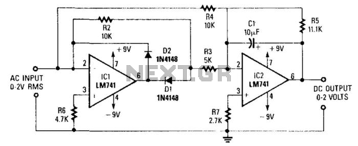
A DC level is generated that corresponds to the AC input RMS value (for a sine wave). The gain of the integrated circuit (IC) is set to a factor of 2 to 1.11. This factor represents the average-to-RMS conversion...
This is a general purpose serial port infrared receiver. With the help of appropriate software, you can control different functions of your PC from a distance. For example, you can control your home cinema settings (volume, play, pause, stop,...