
SW Receiver Using MK414

The described tuned circuit is a fundamental component commonly used in radio frequency (RF) applications, particularly in radio receivers. The circuit consists of two primary elements: a variable capacitor and a fixed air-spaced coil.
The variable capacitor allows for fine-tuning of the circuit's resonant frequency, with a tuning range of 0 to 300 picofarads (pF). This range is suitable for adjusting the circuit to select different radio frequencies, enabling the reception of various broadcasts. The choice of a variable capacitor with a wide tuning range provides flexibility for experimentation with different frequencies and signal strengths.
The coil is constructed using 10 to 20 turns of insulated wire wound around a cylindrical tube with a diameter of approximately 1.5 inches. The spacing of the turns is critical, as it influences the inductance of the coil. The overall length of the coil is about 3 inches, which is a typical dimension for creating a resonant circuit at moderate frequencies. The air-spaced design of the coil minimizes parasitic capacitance, which can affect tuning accuracy and circuit performance.
To complete the circuit, an external antenna is necessary for effective signal reception. The suggested antenna is a wire approximately 7 meters long, which is a practical length for many RF applications. The antenna captures electromagnetic waves from the air, and when properly tuned with the variable capacitor, the circuit can resonate at the desired frequency, allowing for efficient signal processing.
Overall, this tuned circuit design is a versatile platform for exploring radio frequency applications, with ample opportunities for modifications and enhancements based on specific needs or experimental goals.The tuned circuit consists of a variable capacitor and fixed air spaced coil. For the coil, I wound between 10 and 20 turns of wire on an empty tube of around 1.5 inches diameter. The turns were spaced so that the overall length was around 3 inches. The variable capacitor tuned 0 - 300 pF but there is plenty of scope for experiment here. One final point, you will need an external antenna to receive broadcasts. I have an outside wire that is about 7 meters long and this was quite effective. 🔗 External reference
Related Circuits
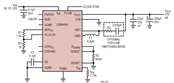
A very simple, high-efficiency switching mode buck-boost power supply circuit can be designed using the LTM4609 switching regulator IC. This circuit will provide a fixed output voltage of 12 volts. As illustrated in the schematic, the switching power supply...
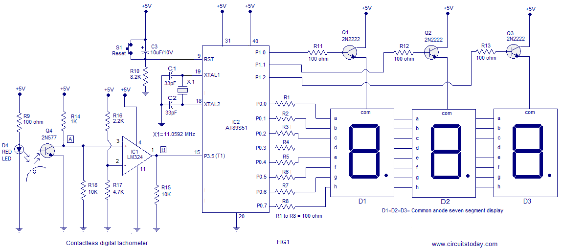
A three-digit contactless digital tachometer utilizing an 8051 microcontroller is presented for measuring the revolutions per second of rotating objects such as wheels, discs, or shafts. The tachometer can measure up to a maximum of 255 revolutions per second...

Design a low-cost 4- to 20-mA receiver circuit for control loops using an analog-to-digital converter (ADC). The design of a low-cost 4- to 20-mA receiver circuit is essential in industrial applications for monitoring and controlling processes. This current loop standard...
This receiver operates within the frequency range of 8.5 to 11.5 MHz across two distinct bands and exhibits a sensitivity level of less than 1 µV. The NE602 mixer is utilized to feed a 455 kHz intermediate frequency (IF)...
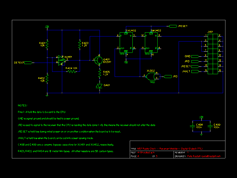
This document describes an earlier version of a project that has been found to be quite unreliable. The project is ongoing, with periodic updates being posted until a proper design and rig are developed, at which point a new...
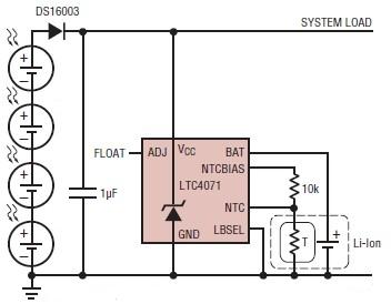
A simple solar-powered battery charger circuit can be designed using the LTC4071 Li-Ion/Polymer Shunt Battery Charger System with Low Battery Disconnect. When VCC reaches the programmed float voltage (4.1V with ADJ floating), the LTC4071 shunts excess current not used...