
HF linear amplifier circuit
The power amplifier output Pi section is a critical component in high-frequency RF applications, where precise tuning and efficient power transfer are essential. The use of variable capacitors allows for fine-tuning of the circuit to achieve optimal performance across different frequency bands. The custom capacitor's design, activated by a relay, enhances versatility, enabling the amplifier to operate effectively in lower frequency ranges.
The anode choke serves to stabilize the high-voltage output, ensuring that the circuit maintains a consistent performance under varying load conditions. The choice of materials, such as the PTFE tube for the choke, is important for maintaining insulation and minimizing losses. The connection between the choke and the doorknob capacitor through a brass ferrule ensures a robust mechanical and electrical link, which is essential for high-power applications.
Airflow management within the grid compartment is crucial for thermal regulation, as excessive heat can lead to component failure. The design allows for effective cooling, with the fan facilitating airflow that aids in dissipating heat generated during operation. The strategic placement of holes around the grid bases ensures that air is efficiently channeled through the PA chimneys, promoting optimal thermal performance.
The heater and cathode connections, made from brass strips, are chosen for their low resistance and good conductivity, essential for maintaining the reliability of the heating circuit. The bifilar winding of the heater choke on a ferrite rod enhances inductance while minimizing electromagnetic interference, which is particularly important in RF circuits.
The inclusion of a non-inductive resistor in the input circuit is a standard practice to prevent reflections and ensure a smooth impedance match. The 100-ohm value aligns with the grid load, optimizing the input VSWR and enhancing the overall efficiency of the amplifier. This careful consideration of component selection and circuit design contributes to a robust, high-performance power amplifier suitable for demanding RF applications.The PA output Pi section consists of 2 variable Cs (20 - 120pF and a second (home made) 50 - 450pF switched in for the lower bands by a simply modified 12v power relay). The anode choke (200t, 24swg 5" long on 1" dia PTFE tube stock) is mounted directly onto a 3300pF 10kV doorknob capacitor using a small turned brass ferule.
The grid compartment. The main fan blows into the sealed grid compartment, and exits through holes around the grid bases to flow through the PA chimneys. The heater/cathode connections are again made from thin brass strip. The heater choke is wound on ferrite rod (from a scrap transistor radio, bifilar 28t 10swg). The input circuit consists of a 100ohm non-inductive 50Watt resistor (Farnell - about £3) directly across the input.
The grid load is also about 100ohm under normal operating conditions so the input VSWR should be quite good. 🔗 External reference
Related Circuits
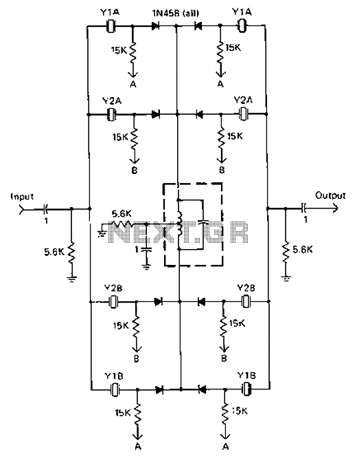
A 9-12V DC power supply is connected to control point A or point B for an amateur communication receiver IF amplifier, offering two distinct options. The power frequency is set at 455 kHz with a bandwidth of 500 Hz....
This classic tube amplifier was once considered the best value available. Fifteen years ago, it could be purchased for $25. The amplifier was designed to be affordable while maximizing performance for the cost. At the end of its production,...

This is a circuit design for an FSK demodulator, which is an electronic device that converts an FSK signal into a serial digital signal. FSK modulation is used to transmit digital serial data, and demodulation is necessary to retrieve...

The schematic illustrates the design of a circuit that measures the resistance of the skin and transforms it into a functional switching signal. This circuit typically employs a resistive sensor, often referred to as a skin resistance sensor or galvanic...
This circuit illustrates a 2W RF amplifier based on the M/A-Com LF2810A MOSFET. The transistor is rated for 10 watts at 28 volts. The 2W RF amplifier circuit utilizing the M/A-Com LF2810A MOSFET is designed to amplify radio frequency signals...
An electronic lock utilizing a telephone key, which is connected through a resistor plug, is integrated after the oscillator circuit's startup phase. The accuracy of the oscillation frequency determines whether the phone can be used for outgoing calls, while...