
MOSFET LF2810 IC For 2W RF Amplifier Circuit diagram
The 2W RF amplifier circuit utilizing the M/A-Com LF2810A MOSFET is designed to amplify radio frequency signals efficiently. The LF2810A is a high-performance transistor capable of handling up to 10 watts of output power, making it suitable for various RF applications.
The circuit typically includes several key components: the MOSFET itself, biasing resistors, input and output matching networks, and power supply connections. The input matching network is crucial for maximizing power transfer from the source to the transistor, while the output matching network ensures that the amplified signal is efficiently delivered to the load, minimizing reflections and losses.
Biasing is essential to set the operating point of the MOSFET, ensuring it operates in the desired region of its characteristics for linear amplification. Resistors are used to establish the proper gate-source voltage, which controls the conduction of the MOSFET.
The overall design may also incorporate decoupling capacitors to filter out unwanted noise and stabilize the power supply, enhancing the amplifier's performance. Thermal management strategies, such as heat sinks, may be included to dissipate heat generated during operation, ensuring reliability and longevity of the circuit.
This type of RF amplifier circuit is commonly used in applications such as wireless communication systems, where signal integrity and amplification are critical for effective transmission and reception of radio signals.This circuit shows a 2W RF amplifier circuit . This amplifier is based on the M/A-Com LF2810A MOSFET. The transistor is actually a 10 watt, 28 .. 🔗 External reference
Related Circuits
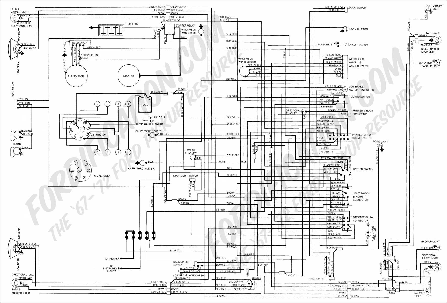
The vehicle is a 1968 Ford equipped with a 1972 engine. The original alternator has been replaced with a new unit. It has been suggested that reversing the polarity of the voltage regulator is necessary for the alternator to...
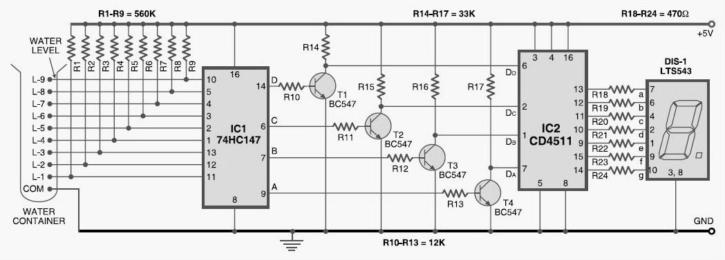
A simple tool to check the degree of radiation from an electric or electronic instrument. The LEDs in the circuit will provide a running light pattern when the circuit detects electromagnetic radiation from the device. It can identify radiation...
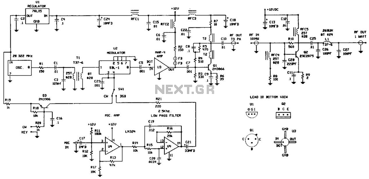
This circuit was detailed in a recent edition of an amateur radio magazine. It enables operation in the 160 to 190 kHz band with a maximum power output of 1 W (license-free) in various modes such as CW, SSB,...
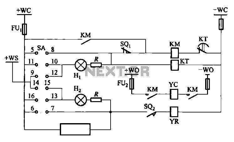
The DW10M de-excitation type switch is based on the DW10 automatic air circuit breaker, transitioning from normally open to normally closed contact. The models available include DW10M-200, DW10M-400, and DW10M-600. The control circuit for this type switch is illustrated...
The video amplifier depicted in the diagram is a well-established design that is both simple and effective. However, there is a risk of damaging the transistors if the potentiometers (black level and signal amplitude) are set to their extreme...
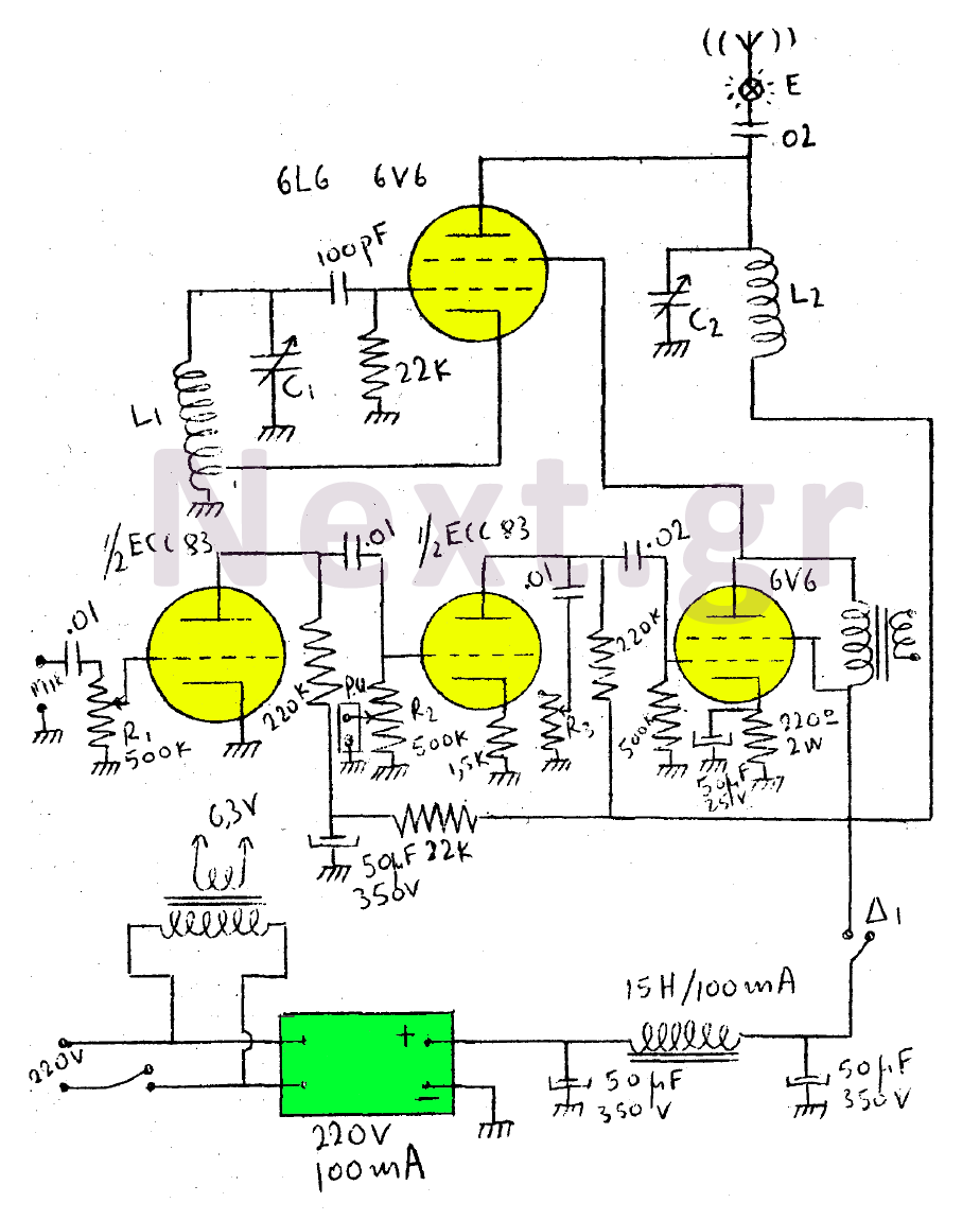
This circuit features a wearer assembly that includes a single lamp, either a 6V6 or 6L6, functioning as both an oscillator and an output amplifier. Coil L1 serves as the medium wave oscillation coil, while coil L2 is composed...
Warning: include(partials/cookie-banner.php): Failed to open stream: Permission denied in /var/www/html/nextgr/view-circuit.php on line 713
Warning: include(): Failed opening 'partials/cookie-banner.php' for inclusion (include_path='.:/usr/share/php') in /var/www/html/nextgr/view-circuit.php on line 713