
Hi Fi Amplifier Circuit 2X12 Watts
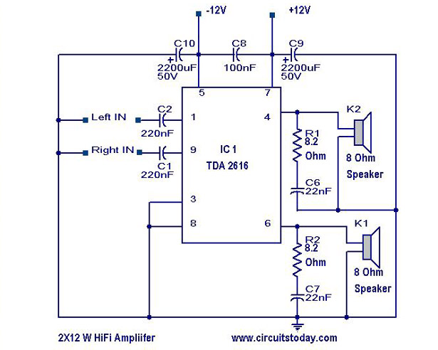
The TDA 2616 is a high-performance integrated circuit designed for audio amplification applications. It is specifically tailored for driving speakers in consumer electronics like radios, tape players, and televisions. The circuit utilizes this IC to achieve a stereo output configuration, allowing it to drive two channels simultaneously.
The amplifier circuit typically includes a power supply section, input signal conditioning, and the TDA 2616 IC configured to operate in a class AB mode. The power supply section should provide a dual voltage supply, often around ±14 to ±16 volts, to ensure optimal performance. The input stage may include capacitors for coupling and resistors for setting the gain, ensuring that the audio signal is appropriately conditioned before amplification.
The TDA 2616 features built-in protections against short circuits and thermal overloads, enhancing the reliability of the circuit. External components such as capacitors and inductors may be included to filter out noise and stabilize the power supply, further improving audio quality.
The output stage of the circuit is designed to deliver 2 x 12 watts of power, which is suitable for driving standard speakers in home audio systems. The design may also include feedback loops to enhance linearity and reduce distortion, ensuring that the amplified audio signal remains faithful to the original input.
In summary, the described Hi-Fi amplifier circuit using the TDA 2616 IC provides a robust solution for audio amplification needs, combining simplicity in design with effective performance for various audio applications.A simple Hi Fi amplifier circuit diagram with schematic for making audio amplifier,design using TDA 2616 IC, which is a stereo power amplifier, useful for radio,tape and television. Delivers 2*12 watts net 24 watts.. 🔗 External reference
Related Circuits

This circuit diagram represents a logic probe based on a single CMOS integrated circuit (IC). The logic probe indicates three conditions: High, Low, and Pulsing. Additionally, no LEDs will illuminate when the probe input is in a high-impedance state,...
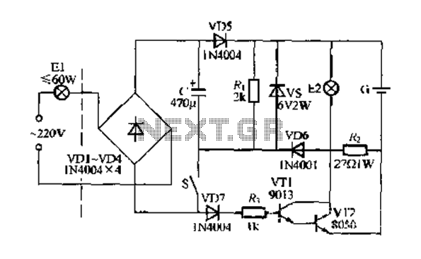
Figure 283 illustrates a blackout emergency lighting controller designed for straightforward external installation with two leads. This controller can directly replace the P Chan Tong Ge opening. Under normal power conditions, it functions like a conventional switch to control...
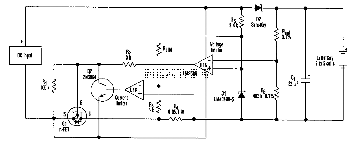
A universal rechargeable lithium battery circuit design, applicable to different battery types and numbers of batteries. This is because both the charger output voltage or current limit setpoint and the maximum charging current can be adjusted by simply changing...
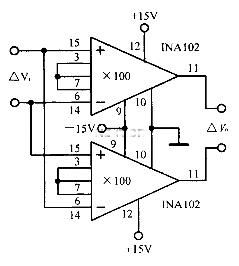
A differential input differential output amplifying circuit diagram. A differential input differential output (DIDO) amplifier is a type of operational amplifier configuration that is designed to amplify the difference between two input signals while rejecting any signals that are common...
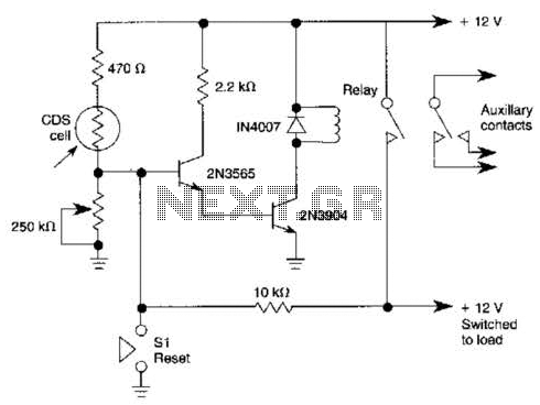
When light strikes the CDS cell, it activates the transistors, which in turn energizes the relay, causing it to latch. Pressing switch SI grounds the base of the 2N3565 transistor, thereby resetting the relay. Additionally, a 250 k potentiometer...
Building a headphone amplifier is like building a power amp - only the current demand is just a little bit lower (about a factor 100). Various designs can be found in the internet, and it is relatively easy to...
Warning: include(partials/cookie-banner.php): Failed to open stream: Permission denied in /var/www/html/nextgr/view-circuit.php on line 713
Warning: include(): Failed opening 'partials/cookie-banner.php' for inclusion (include_path='.:/usr/share/php') in /var/www/html/nextgr/view-circuit.php on line 713